Jeep Liberty KJ. Manual - part 294


  Index      Jeep     Jeep Liberty KJ - service repair manual 2006 year


Search            


Content   ..  292  293  294  295   ..


Jeep Liberty KJ. Manual - part 294


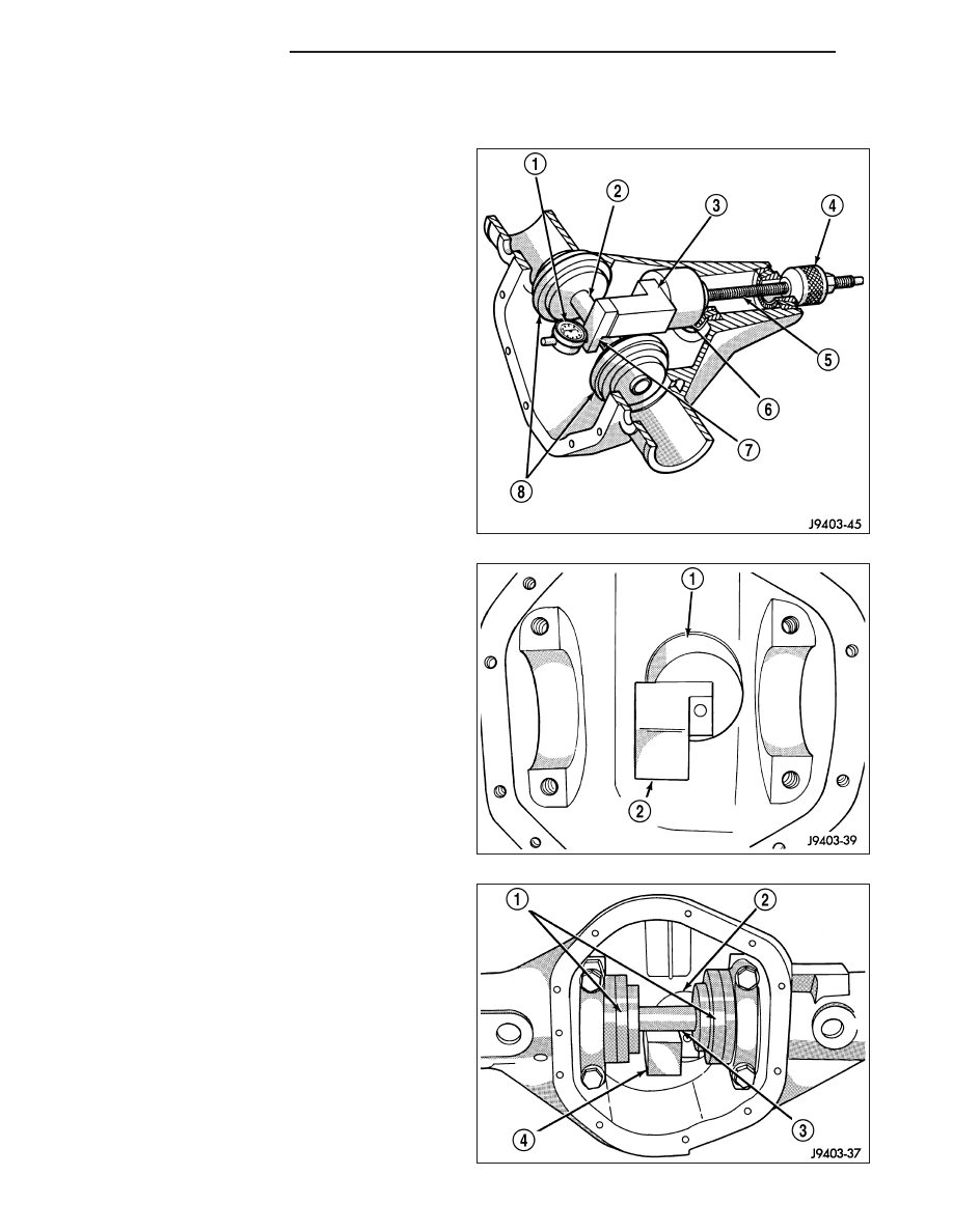
PINION DEPTH MEASUREMENT

Measurements are taken with pinion bearing cups and
pinion bearings installed in the housing. Take mea-
surements with Pinion Gauge Set and Dial Indicator
C-3339 (1).

1. Assemble Pinion Height Block 6739 (2), Pinion

Block 8540 (1) and rear pinion bearing onto Screw
6741.

2. Insert assembled height gauge components, rear

bearing and screw into housing through pinion
bearing cups.

3. Install front pinion bearing and Cone-Nut 6740 on

the screw. Tighten Cone-Nut until Torque To Rotate
screw is 1.7 N·m (15 in. lbs.).

4. Place Arbor Disc 8541 (1) on Arbor D-115-3 (3) in

position in the housing side bearing cradles. Install
differential bearing caps on arbor discs and tighten
cap bolts to 41 N·m (30 ft. lbs.).

3 - 80

REAR AXLE - 8 1/4

KJ

5. Assemble Dial Indicator C-3339 (3) into Scooter

Block D-115-2 (2) and secure set screw.

6. Place Scooter Block/Dial Indicator in position in

axle housing so dial probe and scooter block are
flush against the rearward surface of the pinion
height block. Hold scooter block in place and zero
the dial indicator. Tighten dial indicator face lock
screw.

7. Slowly slide the dial indicator probe over the edge

of the pinion height block.

8. Slide the dial indicator probe across the gap

between the pinion height block and the arbor bar
(1) with the scooter block against the pinion height
block. When dial probe contacts the arbor bar, the
dial pointer will turn clockwise. Continue moving
the dial probe to the crest of the arbor bar and
record the highest reading. If the dial indicator can not achieve a zero reading, the rear bearing cup or the pinion
depth gauge set is not installed correctly.

9. Select a shim equal to the dial indicator reading, plus the drive pinion gear depth variance number marked on

the shaft of the pinion. For example, if the depth variance is –2, add +0.002 in. to the dial indicator reading. Then
subtract 0.041 mm (0.0016 in.) from the total measurement. This will be the correct shim selection for the pinion
height.

DIFFERENTIAL BEARING PRELOAD AND GEAR BACKLASH

The following must be considered when adjusting
bearing preload and gear backlash :

The maximum ring gear (2) backlash variation is
0.076 mm (0.003 in.).

Mark the gears so the same teeth are meshed
during all backlash measurements.

Maintain the torque while adjusting the bearing
preload and ring gear backlash.

Excessive adjuster torque will introduce a high
bearing load and cause premature bearing fail-
ure. Insufficient adjuster torque can result in
excessive differential case free-play and ring
gear noise.

Insufficient adjuster torque will not support the
ring gear correctly and can cause excessive dif-
ferential case free-play and ring gear noise.

NOTE: The differential bearing cups will not
always immediately follow the threaded adjusters
as they are moved during adjustment. To ensure
accurate bearing cup responses to the adjust-
ments:

Maintain the gear teeth engaged (meshed) as marked.

The bearings must be seated by rapidly rotating the pinion gear a half turn back and forth.

Do this five to ten times each time the threaded adjusters are adjusted.

1. Use Adjuster C-4164 to adjust each threaded adjuster inward until the differential bearing free-play is eliminated.

Allow some ring gear backlash, approximately 0.25 mm (0.01 in.) between the ring and pinion gear. Seat the
bearing cups with the procedure described above.

2. Install dial indicator (1) and position the plunger against the drive side of a ring gear tooth (2). Measure the

backlash at 4 positions (90 degrees apart) around the ring gear. Locate and mark the area of minimum backlash.

KJ

REAR AXLE - 8 1/4

3 - 81

3. Rotate the ring gear to the position of the least backlash. Mark the gear so that all future backlash measure-

ments will be taken with the same gear teeth meshed.

4. Loosen the right-side, tighten the left-side threaded adjuster. Obtain backlash of 0.076 to 0.102 mm (0.003 to

0.004 in.) with each adjuster tightened to 14 N·m (10 ft. lbs.). Seat the bearing cups with the procedure
described above.

5. Tighten the differential bearing cap bolts to 95 N·m (70 ft. lbs.).

6. Tighten the right-side threaded adjuster to 102 N·m (75 ft. lbs.). Seat the bearing cups with the procedure

described above. Continue to tighten the right-side adjuster and seat bearing cups until the torque remains con-
stant at 102 N·m (75 ft. lbs.)

7. Measure the ring gear backlash. The range of backlash is 0.12 to 0.20 mm (0.005 to 0.008 in.).

8. Continue increasing the torque at the right-side threaded adjuster until the specified backlash is obtained.

NOTE: The left-side threaded adjuster torque should have approximately 102 N·m (75 ft. lbs.). If the torque
is considerably less, the complete adjustment procedure must be repeated.

9. Tighten the left-side threaded adjuster until 102 N·m (75 ft. lbs.) torque is indicated. Seat the bearing rollers with

the procedure described above. Do this until the torque remains constant.

10. Install the threaded adjuster locks and tighten the lock screws to 10 N·m (90 in. lbs.).

After the proper backlash is achieved, perform the Gear Contact procedure.

GEAR CONTACT PATTERN

1. Wipe clean each tooth of the ring gear.

2. Apply gear marking compound to all of the ring

gear teeth.

3. Verify bearing cap bolts are torque specification.

4. Apply parking brakes lightly to create at 14 N·m (10

ft. lbs.) pinion rotating torque.

5. Rotate the pinion/pinion yoke 4 full revolutions in

each directions.

6. Read gear tooth contact pattern.

Gear contact pattern is correct. Backlash and pinion
depth is correct.

Ring gear is too far away from the pinion gear, coast
side toe (1) drive side heel (2). Decrease backlash by
moving ring closer to the pinion gear using the
adjusters.

3 - 82

REAR AXLE - 8 1/4

KJ

Ring gear is too close to the pinion gear, drive side
toe (1) coast side heel (2). Increase backlash by mov-
ing ring away from the pinion gear using the adjusters.

Ring gear is too far away from the pinion gear, drive
side heel (1) coast side heel (2). Decrease backlash
by moving ring gear closer to the pinion gear using
the adjusters.

Ring gear is too close to the pinion gear, drive side
toe (1) coast side toe (2). Increase backlash by mov-
ing ring gear away from the pinion gear using the
adjusters.

Pinion gear is set too low. Increase pinion gear height,
by increasing pinion depth shim thickness.

KJ

REAR AXLE - 8 1/4

3 - 83


Content   ..  292  293  294  295   ..