Jeep Liberty KJ. Manual - part 275


  Index      Jeep     Jeep Liberty KJ - service repair manual 2006 year


Search            


Content   ..  273  274  275  276   ..


Jeep Liberty KJ. Manual - part 275


UK SECURITY SYSTEM MODULE

DESCRIPTION

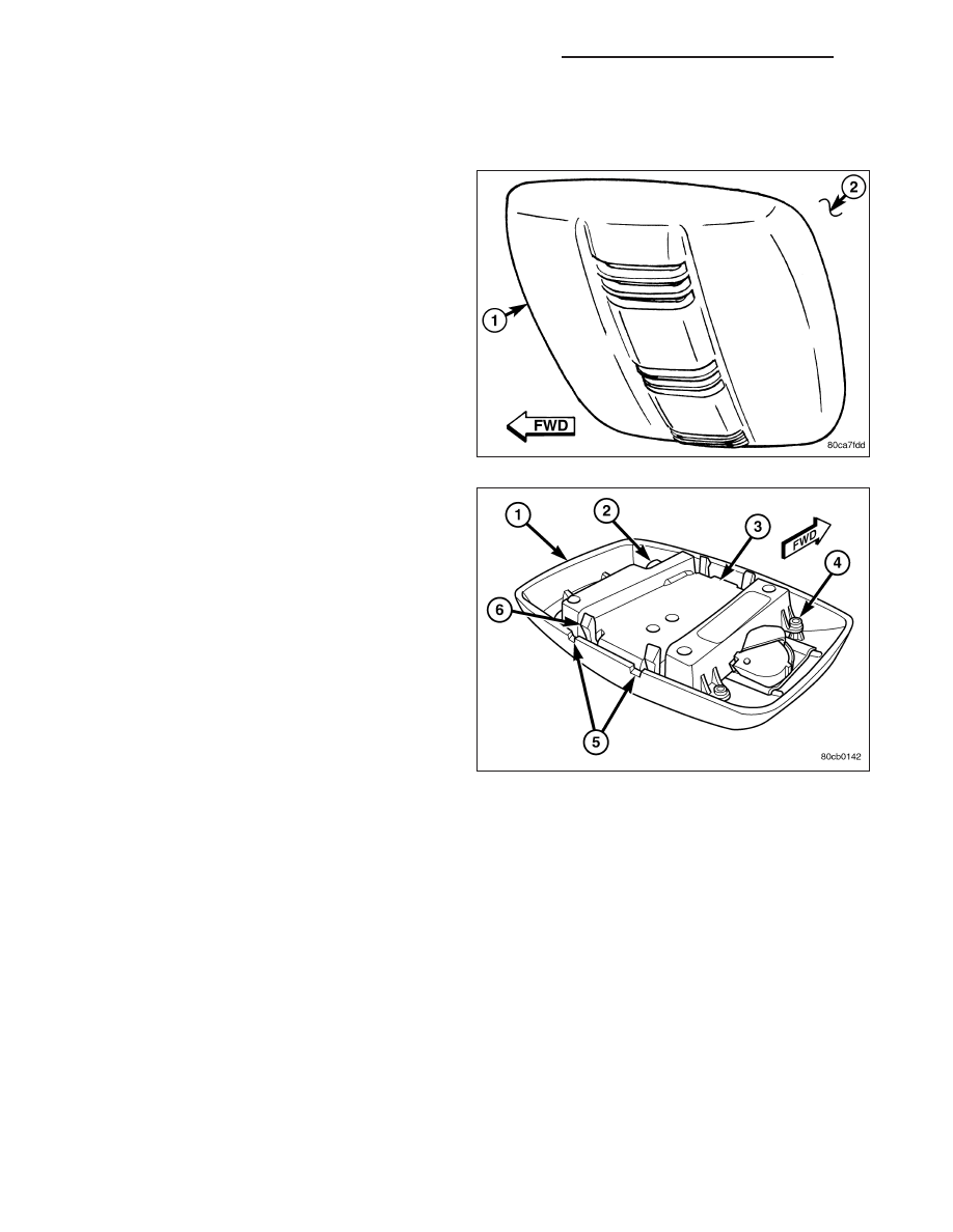
An Intrusion Transceiver Module (ITM) (1) is part of
the export premium version of the Vehicle Theft Alarm
(VTA) in the Vehicle Theft Security System (VTSS).
The export premium version of the VTA is only avail-
able in vehicles built for certain export markets, where
the additional features offered by this system are
required. The ITM is located in the passenger com-
partment, on the lower surface of the headliner (2)
near the center of the vehicle. This component is
designed to provide interior motion detection, and
serve as an interface between the Body Control Mod-
ule (BCM) and the alarm siren module.

The ITM is concealed beneath a molded plastic trim
cover (1) that approximates the size and shape of a
typical dome lamp housing. Rather than a lens, the
trim cover features three sets of louvered openings.
Each of the louvered openings is covered on the
inside by a single molded black plastic sight shield
that extends the length of the center rib for appear-
ance. The entire module is secured to a molded plas-
tic mounting bracket above the headliner. Besides the
ITM, the trim cover also conceals two plastic pins inte-
gral to the mounting bracket that are used to secure
the bracket to the headliner with two stamped nuts
that are installed from below. An adhesive-backed
foam pad is installed above the ITM bracket between
the headliner and the roof panel to provide additional
headliner stabilization and support for the ITM mount-
ing. Two small notch-like service holes (5) on the rear
edge of the trim cover afford access to the two integral rear latches (6) of the ITM housing (3) for service removal.

Concealed within the housing is the electronic circuitry of the ITM which includes a microprocessor, and an ultra-
sonic receive transducer. A molded plastic connector receptacle (2) containing six terminal pins that is soldered to a
small circuit board and extends through a clearance hole in the left front corner of the ITM housing, and an ultra-
sonic transmit transducer housing extends from the center of the right side of the ITM housing. Both the transmit
transducer on the right side of the module and the receive transducer on the ITM circuit board are aimed through
two small round holes in the sight shield of the trim cover. The ITM is connected to the vehicle electrical system by
a wire harness that is integral to the headliner.

The ITM unit cannot be adjusted or repaired and, if inoperative or damaged, it must be replaced.

OPERATION

The microprocessor in the Intrusion Transceiver Module (ITM) contains the motion sensor logic circuits and controls
all of the features of the export premium version of the Vehicle Theft Alarm (VTA). The ITM uses On-Board Diag-
nostics (OBD) and can communicate with other electronic modules in the vehicle as well as with a diagnostic scan
tool using the Programmable Communications Interface (PCI) data bus network. This method of communication is
used by the ITM to communicate with the Body Control Module (BCM) and for diagnosis and testing through the
16-way data link connector located on the driver side lower edge of the instrument panel. The ITM also communi-
cates with the alarm siren module over a dedicated serial bus circuit.

The ITM microprocessor continuously monitors inputs from its on-board motion sensor circuitry as well as inputs
from the BCM and the alarm siren module. The on-board ITM motion sensor circuitry transmits ultrasonic signals

8Q - 76

VEHICLE THEFT SECURITY - SERVICE INFORMATION

KJ

into the vehicle cabin through a transmit transducer, then listens to the returning signals as they bounce off of
objects in the vehicle interior. If an object is moving in the interior, a detection circuit in the ITM senses this move-
ment through the modulation of the returning ultrasonic signals that occurs due to the Doppler effect. The motion
detect function of the ITM can be disabled by depressing the “Lock” button on the Remote Keyless Entry (RKE)
transmitter three times within fifteen seconds, while the VTA is arming (security indicator is still flashing rapidly). The
ITM will signal the alarm siren module to provide a single siren “chirp” as an audible confirmation that the motion
sensor function has been disabled.

If movement is detected, the ITM sends an electronic message to the BCM over the PCI data bus to flash the
exterior lighting and sends an electronic message to the alarm siren module over a dedicated serial bus line to
sound the siren. When the BCM detects a breach in the perimeter protection through a door, tailgate, flip-up glass,
or hood ajar switch input, it sends an electronic message to the ITM and the ITM sends an electronic message to
the BCM over the PCI data bus to flash the exterior lighting and sends an electronic message to the alarm siren
module over a dedicated serial bus line to sound the siren. The ITM also monitors inputs from the alarm siren
module for siren battery or siren input/output circuit tamper alerts, and for siren battery condition alerts, then sets an
active or stored Diagnostic Trouble Code (DTC) for any monitored system faults it detects. An active fault only
remains for the current ignition switch cycle, while a stored fault causes a DTC to be stored in memory by the ITM.
If a fault does not recur for fifty ignition cycles, the ITM will automatically erase the stored DTC.

The ITM is connected to the vehicle electrical system through the overhead wire harness. The ITM receives battery
current through a fuse in the Junction Block (JB), and receives ground through the body wire harness from a ground
screw located at the base of the left D-pillar behind the quarter trim panel. These connections allow the ITM to
remain operational, regardless of the ignition switch position. The hard wired inputs and outputs for the ITM may be
diagnosed and tested using conventional diagnostic tools and procedures. However, conventional diagnostic meth-
ods will not prove conclusive in the diagnosis of the ITM, the PCI data bus, or the electronic message inputs to and
outputs from the ITM. The most reliable, efficient, and accurate means to diagnose the ITM, the PCI data bus, and
the electronic message inputs to and outputs from the ITM requires the use of a diagnostic scan tool. Refer to the
appropriate diagnostic information.

REMOVAL

1. Disconnect and isolate the battery negative cable.

2. While lightly pulling downward on either rear corner

of the Intrusion Transceiver Module (ITM) trim
cover (4), insert a small thin-bladed screwdriver (1)
through each of the service holes (3) on the rear
edge of the trim cover to depress and release the
two integral rear latch features of the module from
the mounting bracket above the headliner (2).

3. Pull the ITM trim cover rearward far enough to dis-

engage the two integral front latch features of the
module from the mounting bracket above the head-
liner.

4. Pull the ITM and trim cover down from the head-

liner far enough to access and disconnect the over-
head wire harness connector for the ITM from the
module connector receptacle.

5. Remove the ITM from the headliner.

KJ

VEHICLE THEFT SECURITY - SERVICE INFORMATION

8Q - 77

INSTALLATION

1. Position the Intrusion Transceiver Module (ITM) to

the headliner (3).

2. Reconnect the overhead wire harness connector

for the ITM to the module connector receptacle.

3. Align the two front latch features of the ITM with

the mounting bracket (2) above the headliner.

4. Push the ITM trim cover forward far enough to

insert the two integral rear latch features of the
module into the two rear latch receptacles (4) of
the mounting bracket above the headliner.

5. Push upward firmly and evenly on the rear edge of

the ITM trim cover until the two rear latch features
of the module are engaged in the mounting bracket
above the headliner.

6. Reconnect the battery negative cable.

NOTE: If the Intrusion Transceiver Module (ITM) has been replaced with a new unit, the new ITM MUST be
initialized before the Vehicle Theft Security System can operate as designed. The use of a diagnostic scan
tool is required to initialize the ITM. Refer to the appropriate diagnostic information.

8Q - 78

VEHICLE THEFT SECURITY - SERVICE INFORMATION

KJ

SENTRY KEY REMOTE ENTRY MODULE

DESCRIPTION

The Sentry Key REmote Entry Module (SKREEM) (1)
is sometimes referred to as the Wireless Control Mod-
ule (WCM). The SKREEM is the primary component of
the Sentry Key Immobilizer System (SKIS) and is also
the receiver for the Remote Keyless Entry (RKE) sys-
tem and the Tire Pressure Monitor (TPM) system. The
SKREEM is located on the right side of the steering
column, near the ignition lock cylinder housing and is
concealed beneath the steering column shrouds. The
molded black plastic housing for the SKREEM has an
integral molded plastic halo-like antenna ring (4) that
extends from one end. When the SKREEM is properly
installed on the steering column, the antenna ring is
oriented around the circumference of the ignition lock
cylinder housing.

A single integral connector receptacle (3) is located on the opposite end of the SKREEM housing from the antenna
ring. A stamped metal mounting bracket (2) secured to the SKREEM housing is used to secure the component to
the right lower flange of the steering column jacket. The SKREEM is connected to the vehicle electrical system
through a single take out and connector of the instrument panel wire harness.

Several SKREEM modules are used, specific to optional vehicle equipment and the market in which the vehicle is
sold. The SKREEM cannot be adjusted or repaired. If inoperative or damaged, the entire SKREEM unit must be
replaced.

OPERATION

The Sentry Key REmote Entry Module (SKREEM) contains a Radio Frequency (RF) transceiver and a micropro-
cessor. The SKIM transmits RF signals to, and receives RF signals from the Sentry Key transponder through a
tuned antenna enclosed within the molded plastic antenna ring integral to the SKREEM housing. If this antenna ring
is not mounted properly around the ignition lock cylinder housing, communication problems between the SKREEM
and the transponder may arise. These communication problems will result in Sentry Key transponder-related faults.

The SKREEM also serves as the Remote Keyless Entry (RKE) and the Tire Pressure Monitor (TPM) RF receiver.
(Refer to 8 - ELECTRICAL/POWER LOCKS - DESCRIPTION) or (Refer to 22 - TIRES/WHEELS/TIRE PRESSURE
MONITORING - DESCRIPTION). The SKREEM communicates over the Programmable Communications Interface
(PCI) data bus with the Body Control Module (BCM), the Electronic Vehicle Information Center (EVIC), the Power-
train Control Module (PCM) or the diagnostic scan tool.

The SKREEM retains in memory the ID numbers of any Sentry Key transponder that is programmed into it. A max-
imum of eight Sentry Key transponders can be programmed into the SKREEM. For added system security, each
SKREEM is programmed with a unique Secret Key code. This code is stored in memory, sent over the PCI data bus
to the PCM, and is encoded to the transponder of every Sentry Key that is programmed into the SKREEM. There-
fore, the Secret Key code is a common element that is found in every component of the Sentry Key Immobilizer
System (SKIS). Another security code, called a PIN, is used to gain access to the SKREEM Secured Access Mode.
The Secured Access Mode is required during service to perform the SKIS initialization and Sentry Key transponder
programming procedures. The SKREEM also stores the Vehicle Identification Number (VIN) in its memory, which it
learns through a PCI data bus message from the PCM during SKIS initialization.

In the event that a SKREEM replacement is required, the Secret Key code can be transferred to the new SKREEM
from the PCM using the diagnostic scan tool and the SKIS initialization procedure. Proper completion of the SKIS
initialization will allow the existing Sentry Keys to be programmed into the new SKREEM so that new keys will not
be required. In the event that the original Secret Key code cannot be recovered, SKREEM replacement will also
require new Sentry Keys. The diagnostic scan tool will alert the technician during the SKIS initialization procedure if
new Sentry Keys are required.

When the ignition switch is turned to the ON position, the SKREEM transmits an RF signal to the transponder in the
ignition key. The SKREEM then waits for an RF signal response from the transponder. If the response received

KJ

VEHICLE THEFT SECURITY - SERVICE INFORMATION

8Q - 79


Content   ..  273  274  275  276   ..