Jeep Liberty KJ. Manual - part 237


  Index      Jeep     Jeep Liberty KJ - service repair manual 2006 year


Search            


Content   ..  235  236  237  238   ..


Jeep Liberty KJ. Manual - part 237


INSTALLATION

WARNING: To avoid personal injury or death, on vehicles equipped with airbags, disable the supplemental
restraint system before attempting any steering wheel, steering column, airbag, occupant classification sys-
tem, seat belt tensioner, impact sensor, or instrument panel component diagnosis or service. Disconnect
and isolate the battery negative (ground) cable, then wait two minutes for the system capacitor to discharge
before performing further diagnosis or service. This is the only sure way to disable the supplemental
restraint system. Failure to take the proper precautions could result in accidental airbag deployment.

WARNING: To avoid personal injury or death, never strike or drop the airbag control module, as it can dam-
age the impact sensor or affect its calibration. The airbag control module contains the impact sensor, which
enables the system to deploy the supplemental restraints. If an airbag control module is accidentally
dropped during service, the module must be scrapped and replaced with a new unit. Failure to observe this
warning could result in accidental, incomplete, or improper supplemental restraint deployment.

CAUTION: On vehicles equipped with the Occupant Classification System (OCS), never replace both the Air-
bag Control Module (ACM) and the Occupant Classification Module (OCM) at the same time. If both require
replacement, replace the OCM first. Then perform the supplemental restraint verification test including an
ignition-On time of at least one minute before replacing the ACM. Both the ACM and the OCM store OCS
calibration data, which they transfer to one another during the first minute of ignition-On time after one of
them is replaced. If both modules are replaced at the same time, an irreversible fault will be set in both
modules. If the data transfer is not allowed sufficient time to complete between modules (at least one
minute of ignition-On), an irreversible fault will be set in the module requiring the data.

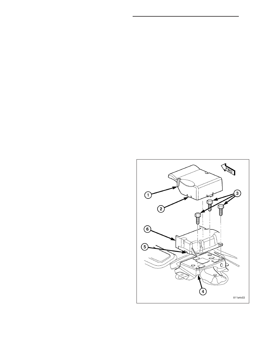
1. Carefully position the Airbag Control Module (ACM)

(6) to the ACM bracket (4) on the floor panel trans-
mission tunnel. When the ACM is correctly posi-
tioned, the arrow on the ACM label will be pointed
forward in the vehicle and the locating pin on the
bottom of the right ACM mounting flange will be
engaged into the locating hole in the ACM bracket.

2. Install and tighten the three screws (3) that secure

the ACM to the ACM bracket that is welded onto
the floor panel transmission tunnel. Tighten the
screws to 11 N·m (8 ft. lbs.).

8O - 254

RESTRAINTS - SERVICE INFORMATION

KJ

CAUTION: The lever arms (2) of the wire harness
connectors for the ACM MUST be in the unlatched
position before they are inserted into their connec-
tor receptacles on the ACM or they may become
damaged.

3. Reconnect the two wire harness connectors (3)

(one each from the instrument panel and the body
wire harnesses) for the ACM (1) to the ACM con-
nector receptacles located on the forward facing
side of the module. Be certain that the latches on
both connectors are each fully engaged.

4. Carefully position the ACM cover back over the top

of the ACM. Be certain both cover latches are
engaged in the slots in the base of the ACM hous-
ing.

5. Reinstall the center console onto the top of the floor panel transmission tunnel. (Refer to 23 - BODY/INTERIOR/

FLOOR CONSOLE - INSTALLATION).

6. Do not reconnect the battery negative cable at this time. The supplemental restraint system verification test pro-

cedure should be performed following service of any supplemental restraint system component. (Refer to 8 -
ELECTRICAL/RESTRAINTS - STANDARD PROCEDURE - VERIFICATION TEST).

KJ

RESTRAINTS - SERVICE INFORMATION

8O - 255

BELT TENSION SENSOR

DESCRIPTION

Vehicles equipped with the Occupant Classification
System (OCS) include a belt tension sensor (1). This
sensor is integral to the passenger side front seat belt
(2) lower anchor which is secured to the outboard side
of the passenger side front seat cushion frame. The
lower anchor and belt tension sensor are concealed
beneath an access cover on the outboard seat cush-
ion side shield on the passenger side front seat. The
belt tension sensor consists of a molded plastic hous-
ing with a central mounting hole (4), a metal seat belt
anchor loop, and a short pigtail wire. The electronic
circuitry of the belt tension sensor is concealed and
protected within the molded plastic housing. The sen-
sor is connected to the vehicle electrical system
through its pigtail wire (3) to a dedicated take out of
the passenger side front seat wire harness with a
keyed and latching molded plastic connector insulator
to ensure a proper and secure connection.

The belt tension sensor cannot be repaired and, if faulty or damaged, the entire passenger side front seat belt and
retractor unit must be replaced. (Refer to 8 - ELECTRICAL/RESTRAINTS/FRONT SEAT BELT & RETRACTOR -
REMOVAL).

OPERATION

The belt tension sensor unit is designed to sense the relative cinch load applied to the passenger side front seat
belt, which provides a logic input to the microprocessor of the Occupant Classification Module (OCM). When a load
is applied to the seat belt, the changes in the load are measured by the belt tension sensor through the seat belt
lower anchor. As the load changes, the circuitry of the belt tension sensor changes the output voltage of the sensor.

The belt tension sensor receives a nominal five volts and a ground through dedicated hard wired circuits from the
OCM. The OCM then monitors the belt tension sensor output voltage on a dedicated hard wired data communica-
tion circuit. The hard wired circuits between the belt tension sensor and the OCM may be diagnosed and tested
using conventional diagnostic tools and procedures. However, the most reliable, efficient, and accurate means to
diagnose the belt tension sensor input to the OCM, and the electronic message communication between the OCM
and the Airbag Control Module (ACM) requires the use of a diagnostic scan tool. Refer to the appropriate diagnostic
information.

8O - 256

RESTRAINTS - SERVICE INFORMATION

KJ

CHILD RESTRAINT ANCHOR

DESCRIPTION

WARNING: To avoid personal injury or death, during and following any seat belt or child restraint anchor
service, carefully inspect all seat belts, buckles, mounting hardware, retractors, tether straps, and anchors
for proper installation, operation, or damage. Replace any belt that is cut, frayed, or torn. Straighten any
belt that is twisted. Tighten any loose fasteners. Replace any belt that has a damaged or inoperative buckle
or retractor. Replace any belt that has a bent or damaged latch plate or anchor plate. Replace any child
restraint anchor or the unit to which the anchor is integral that has been bent or damaged. Never attempt to
repair a seat belt or child restraint component. Always replace damaged or faulty seat belt and child
restraint components with the correct, new and unused replacement parts listed in the DaimlerChrysler
Mopar Parts Catalog.

This model is equipped with a Lower Anchors and Tether for CHildren, or LATCH child restraint anchorage system.
The LATCH system provides for the installation of suitable child restraints in certain seating positions without using
the standard equipment seat belt provided for that seating position. The rear seats in this model are equipped with
a fixed-position child restraint upper tether anchor (2) for both the center and the two outboard seating positions,
and child restraint lower anchors (1) for the two outboard seating positions only.

KJ

RESTRAINTS - SERVICE INFORMATION

8O - 257


Content   ..  235  236  237  238   ..