Jeep Liberty KJ. Manual - part 195


  Index      Jeep     Jeep Liberty KJ - service repair manual 2006 year


Search            


Content   ..  193  194  195  196   ..


Jeep Liberty KJ. Manual - part 195


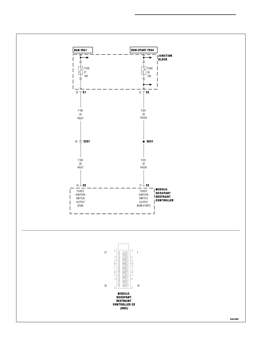
LOSS OF IGNITION RUN ONLY

For a complete wiring diagram Refer to Section 8W.

8O - 86

RESTRAINTS - ELECTRICAL DIAGNOSTICS

KJ

When Monitored:
With the ignition in the Run position.

Set Condition:
The Occupant Restraint Controller (ORC) monitors the voltage of the (F100) Fused Ignition Switch Output
(Run) circuit and will set this DTC if it drops below approximately 6.0 volts.

Possible Causes

(F100) FUSED IGNITION SWITCH OUTPUT (RUN) CIRCUIT SHORTED TO GROUND

IGNITION SWITCH OUTPUT (RUN) CIRCUIT OPEN

(F100) FUSED IGNITION SWITCH OUTPUT (RUN) CIRCUIT OPEN

AIRBAG RUN ONLY CIRCUIT FUSE OPEN

ORC, FUSED IGNITION SWITCH OUTPUT (RUN) CIRCUIT SHORTED TO GROUND

ORC, FUSED IGNITION SWITCH OUTPUT (RUN) CIRCUIT OPEN

Diagnostic Test

1.

DETERMINE ACTIVE OR STORED DTC

NOTE: Ensure that the battery is fully charged.
Turn the ignition on.

Select ACTIVE or STORED DTC:

ACTIVE DTC

Go To 2

STORED DTC

Go To 7

2.

CHECK THE AIRBAG RUN ONLY CIRCUIT FUSE

Turn the ignition off.

Remove and inspect the Airbag Run Only circuit fuse.

NOTE: Check connectors - Clean and repair as necessary.

Is the fuse open?

Yes

>> Go To 3

No

>> Go To 5

3.

CHECK THE (F100) FUSED IGNITION SWITCH OUTPUT (RUN) CIRCUIT RESISTANCE

WARNING: To avoid personal injury or death, turn the ignition off,
disconnect the battery and wait two minutes before proceeding.
Measure the resistance of the (F100) Fused Ignition Switch Output
(Run) circuit between ground and the Airbag Run Only circuit fuse ter-
minal (output side).

Is the resistance below 100.0 ohms?

Yes

>> Go To 4

No

>> Using the wiring diagram/schematic as a guide, inspect the

related wiring and connectors. Look for chafed, pierced,
pinched, or partially broken wires and broken, bent, pushed
out, spread, corroded, or contaminated terminals. Replace
the Airbag Run Only circuit fuse.

Perform *AIRBAG SYSTEM VERIFICATION TEST - VER 1.

KJ

RESTRAINTS - ELECTRICAL DIAGNOSTICS

8O - 87

4.

CHECK THE (F100) FUSED IGNITION SWITCH OUTPUT (RUN) CIRCUIT FOR A SHORT TO GROUND

Disconnect the ORC C2 connector.

NOTE: Check connectors - Clean and repair as necessary.
Connect the appropriate Load Tool Adaptor to the ORC C2 connector.

Measure the resistance of the (F100) Fused Ignition Switch Output
(Run) circuit between ground and the ORC Adapter.

Is the resistance below 100.0 ohms?

Yes

>> Repair the (F100) Fused Ignition Switch Output (Run) circuit

for a short to ground. Replace the Airbag Run Only circuit
fuse.

Perform *AIRBAG SYSTEM VERIFICATION TEST - VER 1.

No

>>

WARNING: If the Occupant Restraint Controller (ORC) is dropped
at any time, it must be replaced. Failure to take the proper precau-
tions could result in accidental airbag deployment and personal
injury or death.

WARNING: To avoid personal injury or death, turn the ignition off,
disconnect the battery and wait two minutes before proceeding.

Replace the ORC in accordance with the Service Informa-
tion. Replace the Airbag Run Only circuit fuse.

Perform *AIRBAG SYSTEM VERIFICATION TEST - VER 1.

5.

CHECK THE IGNITION SWITCH OUTPUT (RUN) CIRCUIT FOR AN OPEN

Turn the ignition on.

Measure the voltage of the Ignition Switch Output (Run) circuit at the
Airbag Run Only circuit fuse terminal (input side).

NOTE: Reinstall the fuse after performing this test.

Is the voltage above 6.0 volts?

Yes

>> Go To 6

No

>> Repair the Ignition Switch Output Run circuit for an open.

Reinstall the Airbag Run Only circuit fuse.

Perform *AIRBAG SYSTEM VERIFICATION TEST - VER 1.

8O - 88

RESTRAINTS - ELECTRICAL DIAGNOSTICS

KJ

6.

CHECK THE (F100) FUSED IGNITION SWITCH OUTPUT (RUN) CIRCUIT FOR AN OPEN

WARNING: To avoid personal injury or death, turn the ignition off,
disconnect the battery and wait two minutes before proceeding.
Disconnect the ORC C2 connector.

NOTE: Check connectors - Clean and repair as necessary.

NOTE: If not done so previously, reinstall the Airbag Run-Start cir-
cuit fuse.
Connect the appropriate Load Tool Adapter to the ORC C2 connector.

NOTE: If not done so previously, reinstall the Airbag Run Only cir-
cuit fuse.

WARNING: To avoid personal injury or death, turn the ignition on,
then, reconnect the battery.
Measure the voltage of the (F100) Fused Ignition Switch Output (Run)
Only circuit.

Is the voltage above 6.0 volts?

Yes

>>

WARNING: If the Occupant Restraint Controller (ORC) is dropped at any time, it must be replaced. Failure to
take the proper precautions could result in accidental airbag deployment and personal injury or death.

Replace the ORC in accordance with the Service Information. Replace the Airbag Run Only circuit fuse.

Perform *AIRBAG SYSTEM VERIFICATION TEST - VER 1.

No

>> Repair the (F23 Fused Ignition Switch Output (Run) circuit for an open.

Perform *AIRBAG SYSTEM VERIFICATION TEST - VER 1.

7.

CHECKING STORED OR INTERMITTENT CODES

NOTE: Diagnose and repair all active codes before diagnosing stored codes. Refer to the Table of Contents
in this Section for a complete list of airbag system diagnostic procedures.
With the scan tool, record and erase all Airbag System Module DTCs.

WARNING: To avoid personal injury or death, turn the ignition off, disconnect the battery and wait two min-
utes before proceeding.
Using the wiring diagram/schematic as a guide, inspect the related wiring and connectors for chafed, pierced,
pinched, and partially broken wires, and for broken, bent, pushed out, corroded, and contaminated terminals. Repair
as necessary.

Reconnect all disconnected components and harness connectors.

WARNING: To avoid personal injury or death, turn the ignition on, then reconnect the battery.
With the scan tool, monitor for active codes while performing the following:

Wiggle the wiring harness and connectors of the related airbag circuit.

Continue the test until either a code becomes active or the problem area is isolated.

In the previous steps you have attempted to recreate the conditions responsible for setting the DTC in question /
causing the intermittent condition.

Are any ACTIVE DTCs present?

Yes

>> Select the appropriate diagnostic procedure from the Table of Contents in this section.

No

>> No problem found at this time. Erase all codes before returning the vehicle to the customer.

KJ

RESTRAINTS - ELECTRICAL DIAGNOSTICS

8O - 89


Content   ..  193  194  195  196   ..