Jeep Liberty KJ. Manual - part 1498


  Index      Jeep     Jeep Liberty KJ - service repair manual 2006 year


Search            


Content   ..  1496  1497  1498  1499   ..


Jeep Liberty KJ. Manual - part 1498


SENSOR - BATTERY TEMPERATURE

DESCRIPTION

The Battery Temperature Sensor (BTS) is attached to the battery tray located under the battery.

OPERATION

The BTS is used to determine the battery temperature and control battery charging rate. This temperature data,
along with data from monitored line voltage, is used by the PCM to vary the battery charging rate. System voltage
will be higher at colder temperatures and is gradually reduced at warmer temperatures.

The PCM sends 5 volts to the sensor and is grounded through the sensor return line. As temperature increases,
resistance in the sensor decreases and the detection voltage at the PCM increases.

The BTS is also used for OBD II diagnostics. Certain faults and OBD II monitors are either enabled or disabled,
depending upon BTS input (for example, disable purge and enable Leak Detection Pump (LDP) and O2 sensor
heater tests). Most OBD II monitors are disabled below 20° F (-7° C).
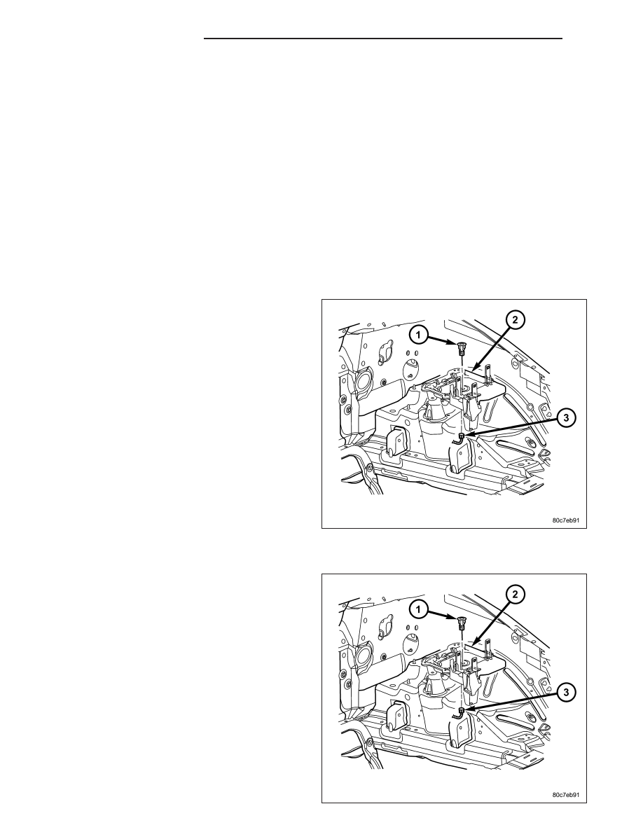
REMOVAL

The battery temperature sensor (1) is located under
the vehicle battery and is attached to a mounting hole
on battery tray.

1. Remove battery. Refer to 8, Battery for procedures.

2. Disconnect sensor pigtail harness from engine wire

harness electrical connector.

3. Pry sensor straight up from battery tray mounting

hole.

INSTALLATION

The battery temperature sensor (1) is located under
vehicle battery and is attached to a mounting hole on
battery tray.

1. Feed pigtail harness through hole in top of battery

tray and press sensor into top of battery tray.

2. Connect pigtail harness.

3. Install battery. Refer to 8, Battery for procedures.

8F - 30

CHARGING SYSTEM

KJ

GENERATOR

DESCRIPTION

The generator is belt-driven by the engine using a serpentine type drive belt. It is serviced only as a complete
assembly. If the generator fails for any reason, the entire assembly must be replaced.

OPERATION

As the energized rotor begins to rotate within the generator, the spinning magnetic field induces a current into the
windings of the stator coil. Once the generator begins producing sufficient current, it also provides the current
needed to energize the rotor.

The stator winding connections deliver the induced AC current to 3 positive and 3 negative diodes for rectification.
From the diodes, rectified DC current is delivered to the vehicle electrical system through the generator battery
terminal.

Although the generators appear the same externally, different generators with different output ratings are used on
this vehicle. Be certain that the replacement generator has the same output rating and part number as the original
unit. Refer to Specifications and see Generator Ratings for amperage ratings and part numbers.

Noise emitting from the generator may be caused by: worn, loose or defective bearings; a loose or defective drive
pulley; incorrect, worn, damaged or misadjusted fan drive belt; loose mounting bolts; a misaligned drive pulley or a
defective stator or diode.

REMOVAL

REMOVAL - GAS

CAUTION: Disconnect negative cable from battery before removing battery output wire from generator. Fail-
ure to do so can result in injury.

1. Disconnect and isolate negative battery cable at battery.

CAUTION: Never force a belt over a pulley rim using a screwdriver. The synthetic fiber of the belt can be
damaged.

CAUTION: When installing a serpentine accessory drive belt, the belt MUST be routed correctly. The water
pump will be rotating in the wrong direction if the belt is installed incorrectly, causing the engine to over-
heat. Refer to belt routing label in engine compartment, or refer to Belt Schematics in Cooling System.

2. Remove generator drive belt. Refer to 7, Cooling System for procedures.

3. Unsnap plastic protective cover (1) from B+ mount-

ing stud.

4. Remove B+ terminal mounting nut (2) at top of

generator.

5. Disconnect field wire electrical connector (4) at rear

of generator by pushing on connector tab.

KJ

CHARGING SYSTEM

8F - 31

6. 2.4L Engine: Remove 2 generator mounting bolts

(1) and (2).

7. 3.7L Engine: Remove 1 vertical generator mounting

bolt (2) and two horizontal mounting bolts (3).

8. Remove generator from vehicle.

REMOVAL- DIESEL

CAUTION: Disconnect negative cable from battery before removing battery output wire from generator. Fail-
ure to do so can result in injury.

CAUTION: Never force a belt over a pulley rim using a screwdriver. The synthetic fiber of the belt can be
damaged.

CAUTION: When installing a serpentine accessory drive belt, the belt MUST be routed correctly. The water
pump will be rotating in the wrong direction if the belt is installed incorrectly, causing the engine to over-
heat. Refer to belt routing label in engine compartment, or refer to Belt Schematics in Cooling System.

1. Disconnect and isolate negative battery cable.

2. Remove engine oil fill cap and engine oil dipstick.

3. Remove plastic decorative engine cover. Cover snaps onto engine.

8F - 32

CHARGING SYSTEM

KJ

4. Remove generator drive belt. Refer to Cooling System for procedure.

5. Remove protective plastic cover from B+ stud at top of generator.

6. Remove nut securing battery output cable to B+ terminal at top of generator.

7. Unplug field terminal connector at rear of generator.

8. Loosen support bracket bolts (3) and nut (2).

9. Remove two generator mounting bolts (2).

10. Remove generator from vehicle.

KJ

CHARGING SYSTEM

8F - 33


Content   ..  1496  1497  1498  1499   ..