Content .. 1482 1483 1484 1485 ..
Jeep Liberty KJ. Manual - part 1484
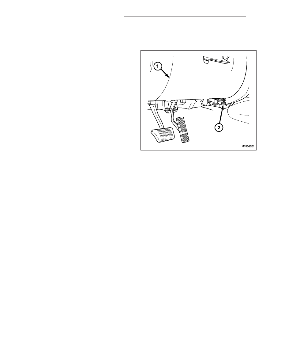
DATA LINK CONNECTOR
DESCRIPTION
The Data Link Connector (DLC) (2) is a 16-way
molded plastic connector insulator on a dedicated take
out of the instrument panel wire harness. This connec-
tor is located at the lower edge of the instrument
panel, inboard of the steering column. The connector
insulator is retained by two screws through two inte-
gral mounting tabs to the lower instrument panel rein-
forcement, just below the lower edge of the instrument
panel steering column opening cover (1).
OPERATION
The Data Link Connector (DLC) is an industry-standard 16-way connector that permits the connection of a diag-
nostic scan tool to the hybrid data bus network for interfacing with, configuring, and retrieving Diagnostic Trouble
Code (DTC) data from the electronic modules that reside on the network within the vehicle.
8E - 148
ELECTRONIC CONTROL MODULES
KJ