Content .. 1440 1441 1442 1443 ..
Jeep Liberty KJ. Manual - part 1442
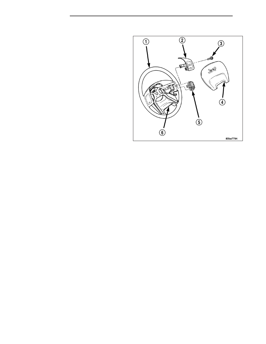
INSTALLATION
WARNING:
Disable
the
airbag
system
before
attempting any steering wheel, steering column,
seat belt tensioner, side airbag, or instrument
panel component diagnosis or service. Disconnect
and isolate the battery negative (ground) cable,
then wait two minutes for the airbag system
capacitor to discharge before performing further
diagnosis or service. This is the only sure way to
disable the airbag system. Failure to take the
proper precautions could result in accidental air-
bag deployment and possible personal injury.
1. Install remote radio switch to the steering wheel.
2. Connect the wire harness to the remote radio
switch.
3. Install the speed control switches.
4. Install the driver side airbag (Refer to 8 - ELECTRI-
CAL/RESTRAINTS/DRIVER AIRBAG - INSTALLA-
TION).
5. Connect the battery negative cable.
8A - 72
AUDIO/VIDEO
KJ