Jeep Liberty KJ. Manual - part 1209


  Index      Jeep     Jeep Liberty KJ - service repair manual 2006 year


Search            


Content   ..  1207  1208  1209  1210   ..


Jeep Liberty KJ. Manual - part 1209


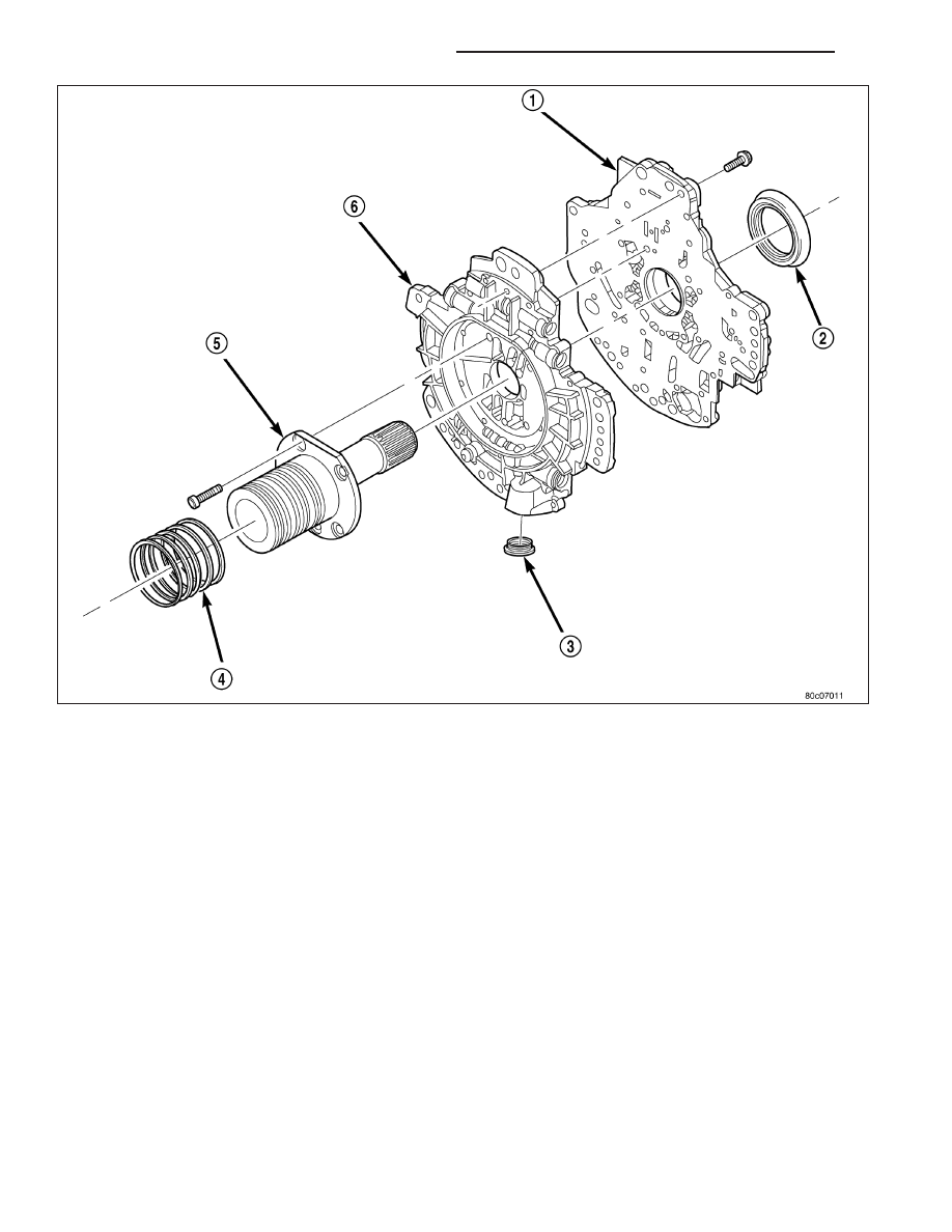
6. Position the oil pump valve body (6) onto the locating dowels.

7. Seat the two oil pump halves together and install all bolts finger tight.

8. Torque all bolts down slowly starting in the center and working outward. The correct torque is 4.5 N·m (40

in.lbs.).

9. Verify that the oil pump gears rotate freely and smoothly.

10. Position the reaction shaft support (5) onto the oil pump valve body (6).

11. Install and torque the bolts to hold the reaction shaft support (5) to the oil pump valve body (6). The correct

torque is 12 N·m (105 in.lbs.).

21 - 780

AUTOMATIC TRANSMISSION - 545RFE

KJ

SEAL-OIL PUMP FRONT

REMOVAL

1. Remove transmission from the vehicle.

2. Remove the torque converter from the transmission.

3. Using a screw mounted in a slide hammer, remove the oil pump front seal.

INSTALLATION

1. Clean seal bore of the oil pump of any residue or

particles from the original seal.

2. Install new oil seal in the oil pump housing using

Seal Installer C-3860-A (1).

KJ

AUTOMATIC TRANSMISSION - 545RFE

21 - 781

SENSOR-OUTPUT SPEED

DESCRIPTION

The Input and Output Speed Sensors are two-wire magnetic pickup devices that generate AC signals as rotation
occurs. They are mounted in the left side of the transmission case and are considered primary inputs to the Trans-
mission Control Module (TCM).

OPERATION

The Input Speed Sensor provides information on how fast the input shaft is rotating. As the teeth of the input clutch
hub pass by the sensor coil, an AC voltage is generated and sent to the TCM. The TCM interprets this information
as input shaft rpm.

The Output Speed Sensor generates an AC signal in a similar fashion, though its coil is excited by rotation of the
rear planetary carrier lugs. The TCM interprets this information as output shaft rpm.

The TCM compares the input and output speed signals to determine the following:

Transmission gear ratio

Speed ratio error detection

CVI calculation

The TCM also compares the input speed signal and the engine speed signal to determine the following:

Torque converter clutch slippage

Torque converter element speed ratio

REMOVAL

1. Raise vehicle.

2. Place a suitable fluid catch pan under the transmis-

sion.

3. Remove the wiring connector from the output

speed sensor (1).

4. Remove the bolt holding the output speed sensor

(1) to the transmission case.

5. Remove the output speed sensor (1) from the

transmission case.

21 - 782

AUTOMATIC TRANSMISSION - 545RFE

KJ

INSTALLATION

1. Install the output speed sensor (1) into the trans-

mission case.

2. Install the bolt to hold the output speed sensor (1)

into the transmission case. Tighten the bolt to 12
N·m (105 in.lbs.).

3. Install the wiring connector onto the output speed

sensor (1).

4. Verify the transmission fluid level. Add fluid as nec-

essary.

5. Lower vehicle.

KJ

AUTOMATIC TRANSMISSION - 545RFE

21 - 783


Content   ..  1207  1208  1209  1210   ..