Jeep Liberty KJ. Manual - part 1188


  Index      Jeep     Jeep Liberty KJ - service repair manual 2006 year


Search            


Content   ..  1186  1187  1188  1189   ..


Jeep Liberty KJ. Manual - part 1188


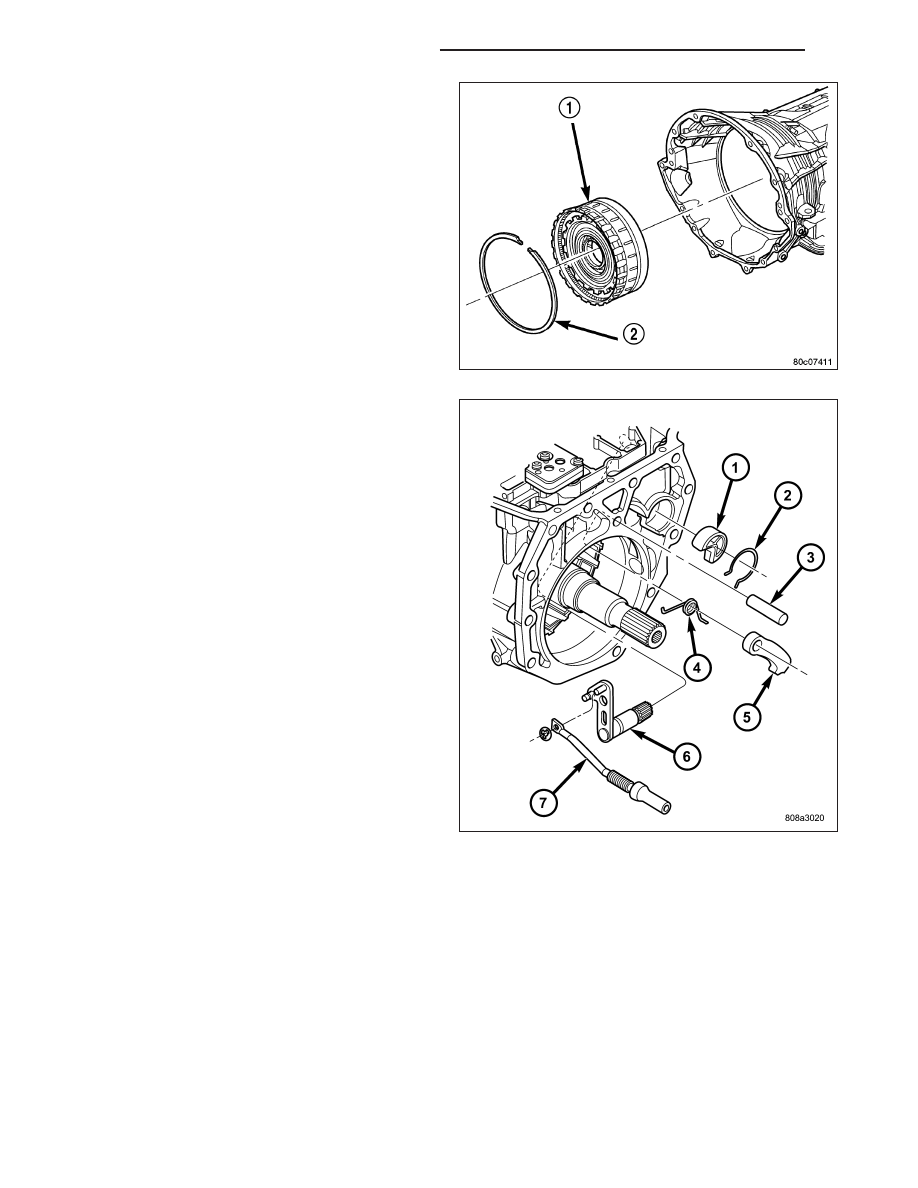
41. Remove the snap-ring (2) holding the low/reverse

clutch retainer (1) into the transmission case.

42. Remove the low/reverse clutch retainer (1) from

the transmission case.

43. Remove the park rod (7) and e-clip.

44. Remove the park rod guide snap-ring (2).

45. Remove the park rod guide (1).

46. Remove the park pawl pivot shaft (3), park pawl

(5), and spring (4).

47. Remove the manual selector shaft (6).

48. Remove the manual selector shaft seal.

49. Remove the dipstick tube seal.

CLEANING

The use of crocus cloth is permissible where necessary, providing it is used carefully. When used on shafts, or
valves, use extreme care to avoid rounding off sharp edges. Sharp edges are vital as they prevent foreign matter
from getting between the valve and valve bore.

Do not reuse oil seals, gaskets, seal rings, or O-rings during overhaul. Replace these parts as a matter of course.
Also do not reuse snap rings or E-clips that are bent or distorted. Replace these parts as well.

Lubricate transmission parts with Mopar

T

ATF +4, Automatic Transmission Fluid, during overhaul and assembly. Use

petroleum jelly, Mopar

T

Door Ease, or Ru-Glyde to prelubricate seals, O-rings, and thrust washers. Petroleum jelly

can also be used to hold parts in place during reassembly.

Clean the case in a solvent tank. Flush the case bores and fluid passages thoroughly with solvent. Dry the case and
all fluid passages with compressed air. Be sure all solvent is removed from the case and that all fluid passages are
clear.

21 - 696

AUTOMATIC TRANSMISSION - 545RFE

KJ

NOTE: Do not use shop towels or rags to dry the case (or any other transmission component) unless they
are made from lint-free materials. Lint will stick to case surfaces and transmission components and circu-
late throughout the transmission after assembly. A sufficient quantity of lint can block fluid passages and
interfere with valve body operation.

INSPECTION

Inspect the case for cracks, porous spots, worn bores, or damaged threads. Damaged threads can be repaired with
Helicoil

T

thread inserts. However, the case will have to be replaced if it exhibits any type of damage or wear.

ASSEMBLY

NOTE: Clean and inspect all components. Replace any components which show evidence of excessive wear
or scoring.

1. Install the cooler filter bypass valve. Torque the

bypass valve to specification. The valve uses a
tapered pipe thread and excessive torque can
damage the transmission case. Tighten the cooler
filter bypass valve to 4.5 N·m (40 in.lbs.).

2. Install a new selector shaft seal (1) using Seal

Installer 8253 (2).

3. Install the manual selector shaft and retaining

screw. Tighten the manual selector shaft retaining
screw to 28 N·m (250 in.lbs.).

4. Install the manual shift lever (1) onto the manual

selector shaft. Torque the retaining cross-bolt to 16
N·m (140 in.lbs.).

KJ

AUTOMATIC TRANSMISSION - 545RFE

21 - 697

5. Install the park pawl (5), spring (4), and shaft (3).

6. Install the park rod (7) and e-clip.

7. Install the park rod guide (1) and snap-ring (2).

8. Install a new dipstick tube seal (2) using Seal

Installer 8254 (1).

21 - 698

AUTOMATIC TRANSMISSION - 545RFE

KJ

NOTE: Before final assembly of transmission cen-
terline, the 2C/4C clutch components should be
installed into position and measured as follows:

9. Install the 2C reaction plate (4) into the transmis-

sion case.

10. Install the 2C clutch pack (2, 3) into the transmis-

sion case.

11. Install the flat 2C clutch snap-ring (1) into the

transmission case.

12. Install the 4C retainer/bulkhead (2) into the trans-

mission case. Make sure that the oil feed holes
are pointing toward the valve body area.

13. Install the 4C retainer/bulkhead tapered snap-ring

(1) into the transmission case. Make sure that the
open ends of the snap-ring are located in the
case opening toward the valve body area.

14. Using a feeler gauge through the opening in the

rear of the transmission case, measure the 2C
clutch pack clearance between the 2C reaction
plate and the transmission case at four different
points. The average of these measurements is the
2C clutch pack clearance. The correct clutch
clearance is 0.455-1.335 mm (0.018-0.053 in.).
The reaction plate is not selective. If the clutch
pack clearance is not within specification, the
reaction plate, all the friction discs, and steels
must be replaced.

15. Remove the 4C retainer/bulkhead and all of the

2C clutch components from the transmission case.

16. Install the low/reverse clutch assembly (1). Make

sure that the oil feed hole points toward the valve
body area and that the bleed orifice is aligned
with the notch in the rear of the transmission
case.

17. Install the snap-ring (2) to hold the low/reverse

clutch retainer into the transmission case. The
snap-ring is tapered and must be installed with
the tapered side forward. Once installed, verify
that the snap-ring is fully seated in the snap-ring
groove.

18. Air check the low/reverse clutch and verify correct

overrunning clutch operation.

KJ

AUTOMATIC TRANSMISSION - 545RFE

21 - 699


Content   ..  1186  1187  1188  1189   ..