Jeep Liberty KJ. Manual - part 1128


  Index      Jeep     Jeep Liberty KJ - service repair manual 2006 year


Search            


Content   ..  1126  1127  1128  1129   ..


Jeep Liberty KJ. Manual - part 1128


Compare the scan tool readings with the numbers listed on the Transmission Simulator.

Do the readings on the Transmission Simulator match the scan tool readings ± 0.2 volts?

Yes

>> Replace Transmission Solenoid/TRS Assembly per the Service Information.

Perform 45RFE/545RFE TRANSMISSION VERIFICATION TEST - VER 1. (Refer to 21 - TRANSMIS-
SION/TRANSAXLE/AUTOMATIC - 45RFE/545RFE - STANDARD PROCEDURE)

No

>> Go To 4

4.

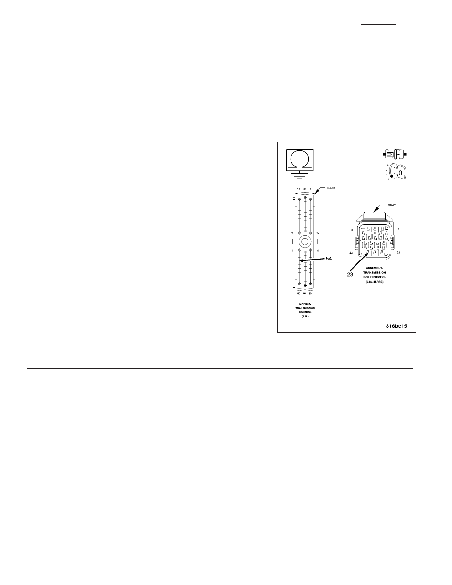
CHECK THE (T54) TRANSMISSION TEMPERATURE SENSOR SIGNAL CIRCUIT FOR A SHORT TO
GROUND

Turn the ignition off to the lock position.

Disconnect the Transmission Simulator, Miller tool #8333.

Disconnect the TCM harness connector.

Measure the resistance between ground and the (T54) Transmission
Temperature Sensor Signal circuit.

Is the resistance below 5.0 ohms?

Yes

>> Repair the (T54) Transmission Temperature Sensor Signal

circuit for a short to ground.

Perform 45RFE/545RFE TRANSMISSION VERIFICATION
TEST - VER 1. (Refer to 21 - TRANSMISSION/TRANS-
AXLE/AUTOMATIC - 45RFE/545RFE - STANDARD PRO-
CEDURE)

No

>> Using the schematics as a guide, check the Transmission

Control Module (TCM) terminals for corrosion, damage, or
terminal push out. Pay particular attention to all power and
ground circuits. If no problems are found, replace the TCM
per the Service Information. With the scan tool, perform
QUICK LEARN.

Perform 45RFE/545RFE TRANSMISSION VERIFICATION
TEST - VER 1. (Refer to 21 - TRANSMISSION/TRANS-
AXLE/AUTOMATIC - 45RFE/545RFE - STANDARD PRO-
CEDURE)

5.

CHECK WIRING AND CONNECTORS

The conditions necessary to set this DTC are not present at this time.

Using the schematics as a guide, inspect the wiring and connectors specific to this circuit.

Wiggle the wires while checking for shorted and open circuits.

With the scan tool, check the DTC EVENT DATA to help identify the conditions in which the DTC was set.

Were there any problems found?

Yes

>> Repair as necessary.

Perform 45RFE/545RFE TRANSMISSION VERIFICATION TEST - VER 1. (Refer to 21 - TRANSMIS-
SION/TRANSAXLE/AUTOMATIC - 45RFE/545RFE - STANDARD PROCEDURE)

No

>> Test Complete.

21 - 456

AUTOMATIC TRANSMISSION 545RFE - ELECTRICAL DIAGNOSTICS - (DIESEL)

KJ

P0713-TRANSMISSION TEMPERATURE SENSOR HIGH

For a complete wiring diagram Refer to Section 8W.

KJ

AUTOMATIC TRANSMISSION 545RFE - ELECTRICAL DIAGNOSTICS - (DIESEL)

21 - 457

When Monitored:
Continuously with the ignition on and engine running.

Set Condition:
The DTC will set when the monitored Temperature Sensor voltage rises above 4.94 volts for the period of 0.45
seconds.

Possible Causes

RELATED DTC’S PRESENT

(T54) TRANSMISSION TEMPERATURE SENSOR SIGNAL CIRCUIT SHORT TO OTHER CIRCUITS

TRANSMISSION TEMPERATURE SENSOR

TRANSMISSION CONTROL MODULE

Always perform the 45RFE/545RFE Pre-Diagnostic Troubleshooting procedure before proceeding. (Refer to
21 - TRANSMISSION/TRANSAXLE/AUTOMATIC - 45RFE/545RFE - STANDARD PROCEDURE)

Theory of Operation

The Transmission Temperature Sensor is a variable resistor that changes with temperature, or otherwise known as
a thermister. The temperature of the transmission fluid can affect a variety of electronically controlled transmission
operations such as shift quality, torque converter lock-up, and when and/or if certain OBDII or system self-diagnostic
test are performed. The Transmission Control Module (TCM) substitutes a calculated transmission temperature
value if a fault is detected in the Transmission Temperature Sensor circuit.

Diagnostic Test

1.

CHECK FOR RELATED DTCS

With the scan tool, check Transmission DTC’s.

Are there any line pressure or throttle position sensor DTCs present?

Yes

>> Refer to the Transmission category and perform the appropriate symptom.

No

>> Go To 2

2.

CHECK IF DTC IS CURRENT

With the scan tool, check the STARTS SINCE SET counter for P0713.

NOTE: This counter only applies to the last DTC set.

Is the STARTS SINCE SET counter 2 or less?

Yes

>> Go To 3

No

>> Go To 5

3.

CHECK THE TRANSMISSION TEMPERATURE SENSOR

Turn the ignition off to the lock position.

Remove the Starter Relay.

CAUTION: Removal of the Starter Relay will prevent the vehicle from being started in gear.

WARNING: The Starter Relay must be removed from the PDC. Failure to do so can result in personal injury
or death.

NOTE: Failure to remove the Starter Relay can cause a Transmission - No Response condition.
Install the Transmission Simulator, Miller tool #8333.

Ignition on, engine not running.

With the Transmission Simulator, turn the Input/Output switch to OFF.

With the scan tool, monitor the TRANS TEMP VOLTS while turning the Thermistor Voltage switch to all three posi-
tions on the Transmission Simulator.

21 - 458

AUTOMATIC TRANSMISSION 545RFE - ELECTRICAL DIAGNOSTICS - (DIESEL)

KJ

Compare the scan tool readings with the numbers listed on the Transmission Simulator.

Do the readings on the Transmission Simulator match the scan tool readings ± 0.2 volts?

Yes

>> Replace Transmission Solenoid/TRS Assembly per the Service Information. (Refer to 21 - TRANSMIS-

SION/TRANSAXLE/AUTOMATIC - 45RFE/545RFE/TRANS SOLENOID/TRS ASSY - REMOVAL)

Perform 45RFE/545RFE TRANSMISSION VERIFICATION TEST - VER 1. (Refer to 21 - TRANSMIS-
SION/TRANSAXLE/AUTOMATIC - 45RFE/545RFE - STANDARD PROCEDURE)

No

>> Go To 4

4.

CHECK THE (T54) TRANSMISSION SENSOR SIGNAL CIRCUIT FOR A SHORT TO ANOTHER CIRCUIT

Turn the ignition off to the lock position.

Disconnect the Transmission Simulator, Miller tool #8333.

Disconnect the TCM harness connector.

Measure the resistance between the (T54) Transmission Temperature
Sensor Signal circuit and all other circuits in the Transmission Solenoid/
TRS Assembly harness connector.

Is the resistance below 5.0 ohms between the (T54) Transmis-
sion Temperature Sensor Signal circuit and any other circuit(s)
in the Transmission Solenoid/TRS Assembly harness connec-
tor?

Yes

>> Repair the Transmission Temperature Sensor Signal circuit

for a short to another circuit(s).

Perform 45RFE/545RFE TRANSMISSION VERIFICATION
TEST - VER 1. (Refer to 21 - TRANSMISSION/TRANS-
AXLE/AUTOMATIC - 45RFE/545RFE - STANDARD PRO-
CEDURE)

No

>> Using the schematics as a guide, check the Powertrain Control Module (TCM) terminals for corrosion,

damage, or terminal push out. Pay particular attention to all power and ground circuits. If no problems
are found, replace the TCM per the Service Information. With the scan tool, perform QUICK LEARN.

Perform 45RFE/545RFE TRANSMISSION VERIFICATION TEST - VER 1. (Refer to 21 - TRANSMIS-
SION/TRANSAXLE/AUTOMATIC - 45RFE/545RFE - STANDARD PROCEDURE)

5.

CHECK WIRING AND CONNECTORS

The conditions necessary to set this DTC are not present at this time.

Using the schematics as a guide, inspect the wiring and connectors specific to this circuit.

Wiggle the wires while checking for shorted and open circuits.

With the scan tool, check the DTC EVENT DATA to help identify the conditions in which the DTC was set.

Were there any problems found?

Yes

>> Repair as necessary.

Perform 45RFE/545RFE TRANSMISSION VERIFICATION TEST - VER 1. (Refer to 21 - TRANSMIS-
SION/TRANSAXLE/AUTOMATIC - 45RFE/545RFE - STANDARD PROCEDURE)

No

>> Test Complete.

KJ

AUTOMATIC TRANSMISSION 545RFE - ELECTRICAL DIAGNOSTICS - (DIESEL)

21 - 459


Content   ..  1126  1127  1128  1129   ..