Jeep Liberty KJ. Manual - part 1114


  Index      Jeep     Jeep Liberty KJ - service repair manual 2006 year


Search            


Content   ..  1112  1113  1114  1115   ..


Jeep Liberty KJ. Manual - part 1114


9.

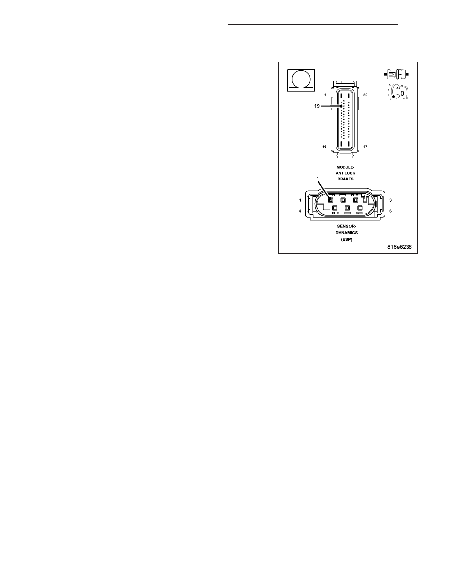
CHECK THE (D51) DYNAMICS SENSOR LOW DATA LINK CIRCUIT FOR AN OPEN

Measure the resistance of the (D51) Dynamics Sensor Low Data Link
circuit between the Dynamics Sensor harness connector and the Anti-
Lock Brakes Module harness connector.

Is the resistance below 5.0 ohms?

Yes

>> Go To 10

No

>> Repair the (D51) Dynamics Sensor Low Data Link circuit for

an open.

Perform ABS VERIFICATION TEST - VER 1. (Refer to 5 -
BRAKES - STANDARD PROCEDURE).

10.

REPLACE DYNAMICS SENSOR & VERIFY IF DTC IS STILL ACTIVE

Replace the Dynamics Sensor in accordance with the Service Information.

Turn the ignition on.

With the scan tool, erase ABS DTCs.

Cycle the ignition switch.

WARNING: Ensure brake capability is available before road testing.
Test drive the vehicle by turning the vehicle left or right in a curving manner at a velocity between 10 and 25 km/hr
(6 and 15 m.p.h.).

Park the vehicle.

With the scan tool, read ABS DTCs.

Does this DTC reset?

Yes

>> Replace the Anti-Lock Brakes Module in accordance with the Service Information.

Perform ABS VERIFICATION TEST - VER 1. (Refer to 5 - BRAKES - STANDARD PROCEDURE).

No

>> Perform ABS VERIFICATION TEST - VER 1. (Refer to 5 - BRAKES - STANDARD PROCEDURE).

5 - 216

BRAKES - ABS ELECTRICAL DIAGNOSTICS

KJ

U0126–LOST COMMUNICATION WITH STEERING ANGLE SENSOR

For a complete wiring diagram Refer to Section 8W.

When Monitored:

With the ignition on

Battery voltage between 10 and 16 volts

IOD fuse installed

Set Condition:
If the Anti-Lock Brakes Module fails to receive bus messages from the Steering Angle Sensor for approxi-
mately 500 ms.

Possible Causes

DTCs RELATED TO BATTERY VOLTAGE, IGNITION, OR VIN MESSAGES

CAN C BUS CIRCUITS OPEN OR SHORTED

STEERING ANGLE SENSOR POWER AND GROUND

STEERING ANGLE SENSOR

ANTI-LOCK BRAKES MODULE

Diagnostic Test

1.

VERIFY DTC IS ACTIVE

NOTE: Ensure the IOD fuse is installed and battery voltage is between 10 and 16 volts before proceeding.
Turn the ignition on.

With the scan tool, read and record ABS DTCs.

With the scan tool, read and record Environmental Data (EV Data).

With the scan tool, erase ABS DTCs.

Cycle the ignition switch.

With the scan tool, read ABS DTCs.

Does this DTC reset?

Yes

>> Go To 2

No

>> Perform the Stored Lost Communication test procedure. (Refer to 8 - ELECTRICAL/ELECTRONIC

CONTROL MODULES - DIAGNOSIS AND TESTING).

2.

CHECK FOR ANY OF THE FOLLOWING ACTIVE DTCs

With the scan tool, read all active DTCs from all CAN C Bus modules.

NOTE: Check for CAN C hardware electrical, VIN Missing/Mismatch, battery or ignition related DTCs.

Does the scan tool display any active DTCs related to the conditions listed above?

Yes

>> Diagnose and repair the DTC(s). Refer to the Table of Contents in the applicable Section.

No

>> Go To 3

KJ

BRAKES - ABS ELECTRICAL DIAGNOSTICS

5 - 217

3.

VERIFY THAT THE STEERING ANGLE SENSOR IS ACTIVE ON THE BUS

With the scan tool, select ECU View.

Verify that the Steering Angle Sensor is active on the bus.

Is the Steering Angle Sensor active on the bus?

Yes

>> Go To 4

No

>> (Refer to 8 - ELECTRICAL/ELECTRONIC CONTROL MODULES - DIAGNOSIS AND TESTING) for No

Response related diagnostic procedures.

4.

CHECK FOR ADDITIONAL COMMUNICATION RELATED DTCs

With the scan tool, select Network View and select Advanced.

Is there more than one module with active DTCs “Logged Against” the STEERING ANGLE SENSOR?

Yes

>> Replace/update the Steering Angle Sensor in accordance with the service information.

Perform ABS VERIFICATION TEST - VER 1. (Refer to 5 - BRAKES - STANDARD PROCEDURE).

No

>> Replace the Anti-Lock Brakes Module in accordance with the service information.

Perform ABS VERIFICATION TEST - VER 1. (Refer to 5 - BRAKES - STANDARD PROCEDURE).

5 - 218

BRAKES - ABS ELECTRICAL DIAGNOSTICS

KJ

U0146–LOST COMMUNICATION WITH CENTRAL GATEWAY

For a complete wiring diagram Refer to Section 8W.

When Monitored:

With the ignition on

Battery voltage between 10 and 16 volts

IOD fuse installed

Set Condition:
If the Anti-Lock Brakes Module either fails to receive bus messages from the Body Control Module (BCM) for
approximately 500 ms, or it receives invalid messages from the BCM, or it detects messages from the BCM
are of improper data length.

Possible Causes

DTCs RELATED TO BATTERY VOLTAGE, IGNITION, OR VIN MESSAGES

CAN C BUS CIRCUITS OPEN OR SHORTED

BCM POWER AND GROUND

BCM

ANTI-LOCK BRAKES MODULE

Diagnostic Test

1.

VERIFY DTC IS ACTIVE

NOTE: Ensure the IOD fuse is installed and battery voltage is between 10 and 16 volts before proceeding.
Turn the ignition on.

With the scan tool, read and record ABS DTCs.

With the scan tool, read and record Environmental Data (EV Data).

With the scan tool, erase ABS DTCs.

Cycle the ignition switch.

With the scan tool, read ABS DTCs.

Does this DTC reset?

Yes

>> Go To 2

No

>> Perform the Stored Lost Communication test procedure. (Refer to 8 - ELECTRICAL/ELECTRONIC

CONTROL MODULES - DIAGNOSIS AND TESTING).

2.

CHECK FOR ANY OF THE FOLLOWING ACTIVE DTCs

With the scan tool, read all active DTCs from all CAN C Bus modules.

NOTE: Check for CAN C hardware electrical, VIN Missing/Mismatch, battery or ignition related DTCs.

Does the scan tool display any active DTCs related to the conditions listed above?

Yes

>> Diagnose and repair the DTC(s). Refer to the Table of Contents in the applicable Section.

No

>> Go To 3

KJ

BRAKES - ABS ELECTRICAL DIAGNOSTICS

5 - 219


Content   ..  1112  1113  1114  1115   ..