Jeep Liberty KJ. Manual - part 1099


  Index      Jeep     Jeep Liberty KJ - service repair manual 2006 year


Search            


Content   ..  1097  1098  1099  1100   ..


Jeep Liberty KJ. Manual - part 1099


3.

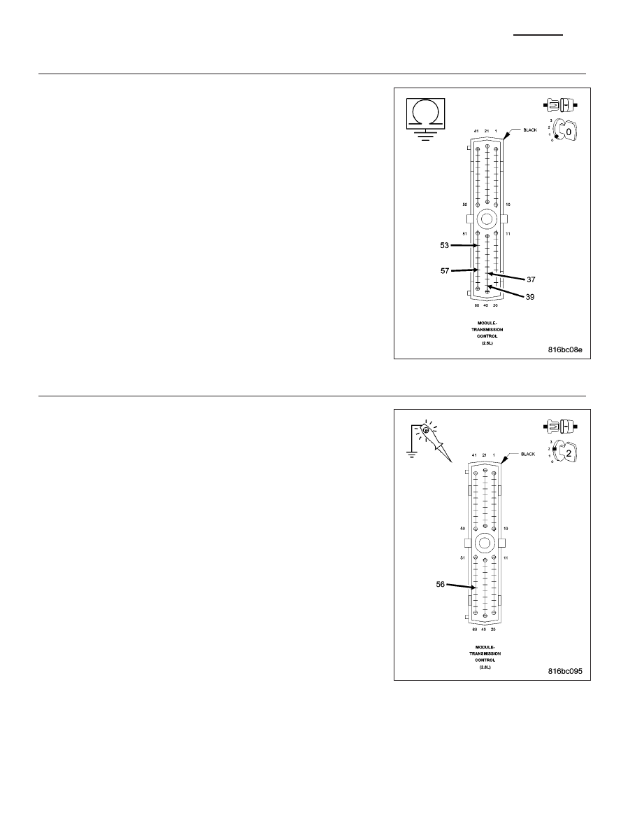
CHECK THE (Z133) GROUND CIRCUITS

Turn the ignition off to the lock position.

Disconnect the TCM harness connector.

NOTE: Check connectors - Clean/repair as necessary.
Using a 12-volt test light connected to 12-volts, check the (Z133)
Ground circuits.

NOTE: The test light must illuminate brightly. Compare the bright-
ness to that of a direct connection to the battery.

Does the test light illuminate brightly for all the (Z133) Ground
circuits?

Yes

>> Go To 4

No

>> Repair the (Z133) Ground circuit(s) for an open or high

resistance.

Perform 45RFE/545RFE TRANSMISSION VERIFICATION
TEST - VER 1. (Refer to 21 - TRANSMISSION/TRANS-
AXLE/AUTOMATIC - 45RFE/545RFE - STANDARD PRO-
CEDURE)

4.

CHECK THE (A903) FUSED B(+) CIRCUIT

Remove the Transmission Control Relay.

Ignition on, engine not running.

Using a 12-volt test light connected to ground, check the (A104) Fused
B(+) circuit at the Transmission Control Relay connector.

Does the test light illuminate brightly?

Yes

>> Go To 5

No

>> Repair the (A104) Fused B(+) circuit for an open or high

resistance.

Perform 45RFE/545RFE TRANSMISSION VERIFICATION
TEST - VER 1. (Refer to 21 - TRANSMISSION/TRANS-
AXLE/AUTOMATIC - 45RFE/545RFE - STANDARD PRO-
CEDURE)

21 - 440

AUTOMATIC TRANSMISSION 545RFE - ELECTRICAL DIAGNOSTICS - (DIESEL)

KJ

5.

CHECK THE (T16) TRANSMISSION CONTROL RELAY OUTPUT CIRCUIT

Turn the ignition off to the lock position.

NOTE: Check connectors - Clean/repair as necessary.
Connect a jumper wire between (A104) Fused B(+) circuit and the (T16)
Transmission Control Relay Output circuit in the Transmission Control
Relay connector.

Ignition on, engine not running.

Using a 12-volt test light connected to ground, check all (T16) Trans-
mission Control Relay Output circuits at the TCM harness connector.

Does the test light illuminate brightly?

Yes

>> Go To 6

No

>> Repair the (T16) Transmission Control Relay Output circuit

for an open or high resistance.

Perform 45RFE/545RFE TRANSMISSION VERIFICATION
TEST - VER 1. (Refer to 21 - TRANSMISSION/TRANS-
AXLE/AUTOMATIC - 45RFE/545RFE - STANDARD PRO-
CEDURE)

6.

CHECK THE TRANSMISSION CONTROL RELAY

Turn the ignition off to the lock position.

Reconnect all previously disconnected connectors.

Install a substitute Relay in place of the Transmission Control Relay.

Start the engine.

Using a voltmeter, measure the vehicles battery voltage.

With the scan tool, monitor the Transmission Switched Battery Voltage.

Compare the scan tool Transmission Switched Battery voltage to the actual battery voltage reading on the voltmeter.

Is the scan tool voltage within 1.0 volt of the battery voltage?

Yes

>> Replace the Transmission Control Relay.

Perform 45RFE/545RFE TRANSMISSION VERIFICATION TEST - VER 1. (Refer to 21 - TRANSMIS-
SION/TRANSAXLE/AUTOMATIC - 45RFE/545RFE - STANDARD PROCEDURE)

No

>> Using the schematics as a guide, check the Transmission Control Module (TCM) terminals for corrosion,

damage, or terminal push out. Pay particular attention to all power and ground circuits. If no problems
are found, replace the TCM per the Service Information. With the scan tool, perform QUICK LEARN.

Perform 45RFE/545RFE TRANSMISSION VERIFICATION TEST - VER 1. (Refer to 21 - TRANSMIS-
SION/TRANSAXLE/AUTOMATIC - 45RFE/545RFE - STANDARD PROCEDURE)

KJ

AUTOMATIC TRANSMISSION 545RFE - ELECTRICAL DIAGNOSTICS - (DIESEL)

21 - 441

7.

CHECK WIRING AND CONNECTORS

The conditions necessary to set this DTC are not present at this time.

Using the schematics as a guide, inspect the wiring and connectors specific to this circuit.

Wiggle the wires while checking for shorted and open circuits.

With the scan tool, check the DTC EVENT DATA to help identify the conditions in which the DTC was set.

Where there any problems found?

Yes

>> Repair as necessary.

Perform 45RFE/545RFE TRANSMISSION VERIFICATION TEST - VER 1. (Refer to 21 - TRANSMIS-
SION/TRANSAXLE/AUTOMATIC - 45RFE/545RFE - STANDARD PROCEDURE)

No

>> Test Complete.

21 - 442

AUTOMATIC TRANSMISSION 545RFE - ELECTRICAL DIAGNOSTICS - (DIESEL)

KJ

P0602-CONTROL MODULE PROGRAMMING ERROR/NOT PROGRAMMED

For a complete wiring diagram Refer to Section 8W

When Monitored:
Check for generic software is made at power-up

Set Condition:
If generic software is found, the MIL will light immediately. This DTC is designed to inform the technician that
the controller still has generic software installed.

Possible Causes

TCM - PROGRAMMING ERROR

Always perform the Pre-Diagnostic Troubleshooting procedure before proceeding. (Refer to 21 - TRANSMIS-
SION/TRANSAXLE/AUTOMATIC - 45RFE/545RFE - STANDARD PROCEDURE)

Theory of Operation

The controller is programmed during manufacturing with generic software to facilitate testing. However, generic soft-
ware does not have the proper calibrations to control a transmission in a vehicle. The check for generic software is
made at power-up. If generic software is found , the MIL will light immediately and the MIL will stay on even if the
fault is cleared, until the proper software is installed. Note: Transmission will be placed in limp-in mode.

Diagnostic Test

1.

CONTROL MODULE PROGRAMMING ERROR

NOTE: Controller is programmed with generic software and will not allow the correct vehicle Powertrain
management.
With the scan tool.

Record the vehicles controller part number.

Select Use Controller Part Number under the Flash Tab.

Flash the controller with the correct software.

Verify the controller flashed successfully.

Test Complete

Perform 45RFE/545RFE TRANSMISSION VERIFICATION TEST - VER 1. (Refer to 21 - TRANSMIS-
SION/TRANSAXLE/AUTOMATIC - 45RFE/545RFE - STANDARD PROCEDURE)

KJ

AUTOMATIC TRANSMISSION 545RFE - ELECTRICAL DIAGNOSTICS - (DIESEL)

21 - 443


Content   ..  1097  1098  1099  1100   ..