Content .. 1080 1081 1082 1083 ..
Jeep Liberty KJ. Manual - part 1082
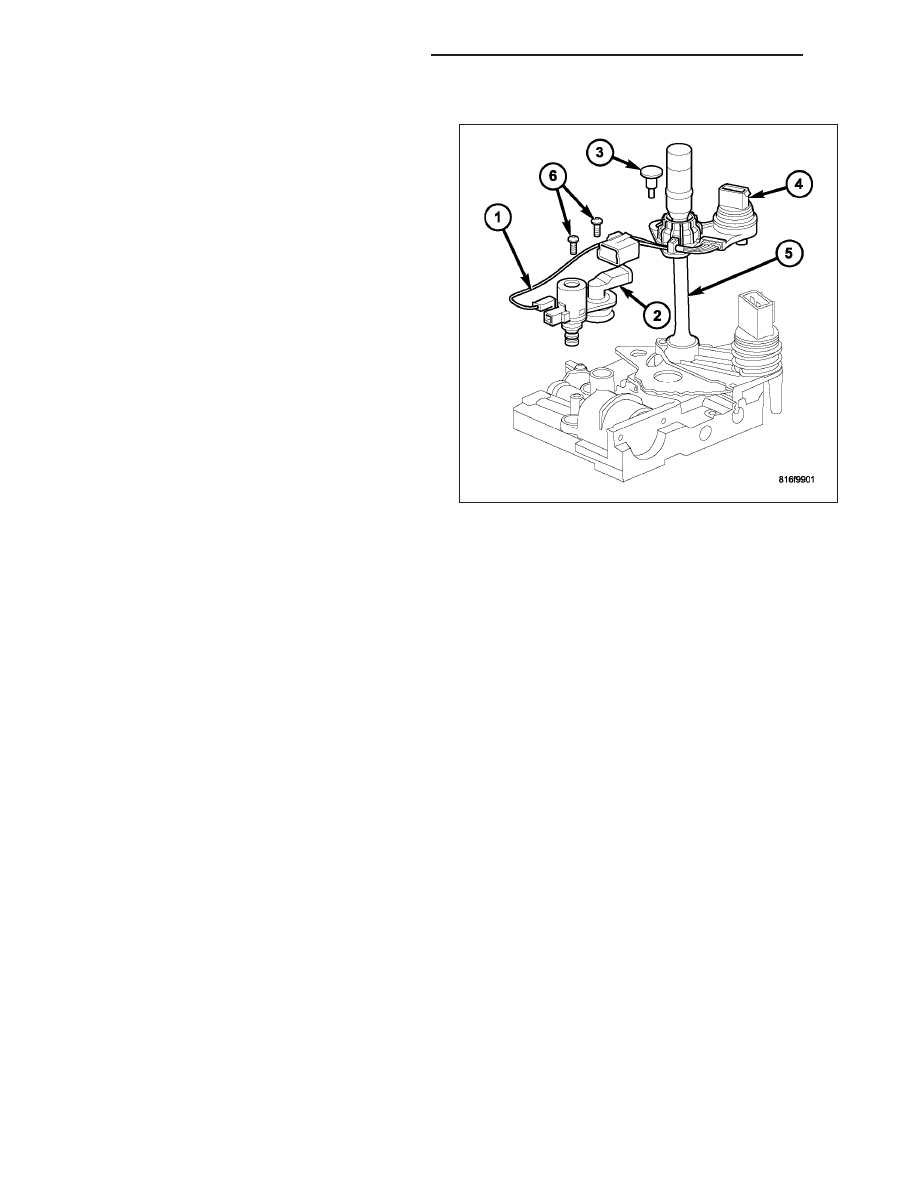
INSTALLATION
1. Install the pressure control solenoid (1) and line
pressure sensor (2) into the valve body.
2. Install the screws (6) to hold the pressure control
solenoid (1) and line pressure sensor (2) to the
valve body.
3. Install the electrical connectors to the pressure
control solenoid (1) and the line pressure sensor
(2).
4. Install the valve body into the transmission. (Refer
to 21 - TRANSMISSION/TRANSAXLE/AUTOMATIC
- 42RLE/VALVE BODY - INSTALLATION)
21 - 372
AUTOMATIC TRANSMISSION - 42RLE
KJ