Jeep Liberty KJ. Manual - part 108


  Index      Jeep     Jeep Liberty KJ - service repair manual 2006 year


Search            


Content   ..  106  107  108  109   ..


Jeep Liberty KJ. Manual - part 108


LAMP

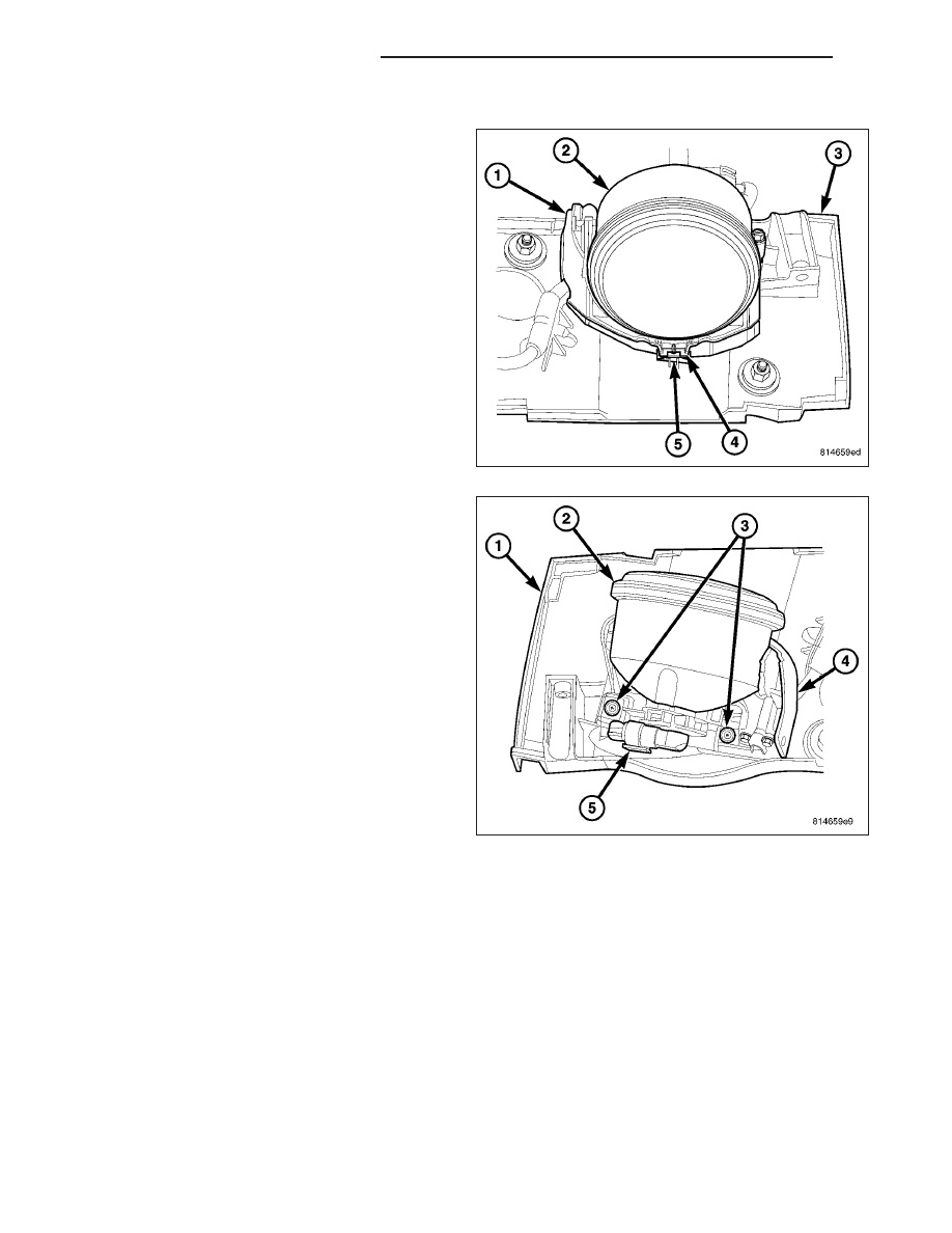
1. Position the lamp (2) and bracket (1) unit onto the

light bar reinforcement (3).

NOTE: There is a hook on the forward edge of the
lamp bracket that must be secured under a tab
that is integral to the reinforcement. The rear of
the lamp must be lifted upward by the lamp sock-
et/connector in order to engage the hook under
the tab.

2. Lift the lamp socket/connector on the rear of the

lamp upward far enough to engage the hook (4) on
the front edge of the lamp bracket under the inte-
gral tab (5) of the reinforcement.

3. Slide the lamp and bracket forward and seat.

4. Install and tighten the two screws (3) that secure

the rear of the lamp bracket (4) to the reinforce-
ment (1). Tighten the screws to 2 N·m (17 in. lbs.).

5. Reconnect the light bar wire harness connector (5)

to the socket on the back of the lamp (2).

6. Reconnect the battery negative cable.

7. Confirm proper lamp alignment. (Refer to 8 -

ELECTRICAL/LAMPS/LIGHTING

-

EXTERIOR/

LIGHT BAR LAMP - ADJUSTMENTS).

8. Reinstall the cover over the light bar lamps and

reinforcement. (Refer to 8 - ELECTRICAL/LAMPS/
LIGHTING

-

EXTERIOR/LIGHT

BAR

LAMP

COVER - INSTALLATION).

8L - 90

LAMPS/LIGHTING - EXTERIOR

KJ

COVER

1. Position the front edge of the light bar cover (1) on

the roof panel just ahead of the front edge of the
light bar reinforcement (3).

2. Slide the cover rearward to engage the front edge

of the cover under the forward edge of the rein-
forcement, then lower the rear edge of the cover
into position.

3. Install and tighten the four screws (2) that secure

the rear edge of the cover to the reinforcement.
Tighten the screws to 2 N·m (17 in. lbs.).

REINFORCEMENT

CAUTION: Four strips of double-faced adhesive tape serve to protect the roof panel and supplement the
hard fasteners that secure the light bar reinforcement. Any residual tape and adhesive must be removed
carefully to prevent damage to roof panel. Following removal, the roof panel and the bottom of the rein-
forcement must be thoroughly cleaned with isopropyl alcohol or another suitable solvent. The mounting
surfaces must be clean and dry before installation.

1. Install four new strips of double-faced adhesive

tape to the base of an existing reinforcement (4)
being reinstalled.

2. Remove the release paper from the adhesive strips

on the base of the new (4) or existing reinforce-
ment.

3. With the aid of an assistant, carefully feed the

jumper wire and connector (2) through the clear-
ance hole in the reinforcement while positioning the
unit over the rivet studs (3) on the roof panel.

4. Using hand pressure, press the reinforcement

down firmly and evenly over each of the tape strips
to be certain they are firmly secured to the roof
panel.

5. Install and tighten the four nuts (1) that secure the

reinforcement to the rivet studs on the roof panel.
Tighten the nuts to 6 N·m (50 in. lbs.).

6. Reconnect the jumper harness connector to the

light bar reinforcement harness connector.

7. Reconnect the battery negative cable.

8. Confirm proper lamp alignment. (Refer to 8 - ELECTRICAL/LAMPS/LIGHTING - EXTERIOR/LIGHT BAR LAMP

- ADJUSTMENTS).

9. Reinstall the cover over the light bar lamps and reinforcement. (Refer to 8 - ELECTRICAL/LAMPS/LIGHTING -

EXTERIOR/LIGHT BAR LAMP COVER - INSTALLATION).

KJ

LAMPS/LIGHTING - EXTERIOR

8L - 91

ADJUSTMENTS

LIGHT BAR LAMP

VEHICLE PREPARATION FOR LIGHT BAR LAMP ALIGNMENT

1. Repair or replace any ineffective or damaged components that could hinder proper lamp alignment.

2. Verify proper tire inflation.

3. Clean light bar lamp lenses.

4. Verify that cargo area is not heavily loaded.

5. The fuel tank should be Full. Add 2.94 kilograms (6.5 pounds) of weight over the fuel tank for each estimated

gallon of missing fuel.

LIGHT BAR LAMP ALIGNMENT SCREEN PREPARATION

1. Position the vehicle on a level surface perpendicular to a flat wall 7.62 meters (25 feet) away from the front of

the headlamp lens. If necessary, tape a line on the floor at the appropriate distance away from and parallel to the
wall.

2. Measure up on the wall 2.36 meters (93 inches) from the floor and tape a horizontal line on the alignment screen

that is approximately as long as the vehicle is wide. This line will be used for the light bar lamp up-and-down
(vertical) adjustment reference.

LIGHT BAR LAMP ADJUSTMENT

NOTE: Only the vertical aim of the light bar lamp beams is adjustable.

1. Rock the vehicle from side-to-side three times to

allow the suspension to stabilize, then jounce the
front suspension three times by pushing downward
on the front bumper and releasing.

2. Turn the adjusting screw (2) on the back of the

light bar lamp (1) until the beam intensity pattern is
centered on the up-and-down (vertical) adjustment
reference tape on the alignment screen.

3. Repeat the adjustment procedure for each lamp as

required.

8L - 92

LAMPS/LIGHTING - EXTERIOR

KJ

LAMP BAR SWITCH

DESCRIPTION

The light bar lamp switch (1) is used only on vehicles
equipped with the optional light bar and off road
lamps. The light bar lamp switch is mounted in the
driver side outboard trim bezel on the instrument
panel. Only the switch bezel and rocker (4) are visible
on the outer surface of the instrument panel trim
bezel. The black plastic switch rocker is marked with
an icon that is similar in appearance to the Interna-
tional Control and Display Symbol icon for “High
Beam”, but has an additional curved line beneath it to
represent the forward roofline of the vehicle. The icon
is illuminated when the exterior lighting is turned On.

The black, molded plastic switch housing encloses the momentary switch rocker mechanism and the switch circuitry
including an integral relay and active electronic elements. A connector receptacle (2) is integral to the back of the
switch housing, while a two integral latch features (3) on the top and bottom of the housing secure the switch in the
instrument panel trim bezel. The switch is connected to the vehicle electrical system through a dedicated take out
and connector of the instrument panel wire harness.

The light bar lamp switch cannot be adjusted or repaired and, if ineffective or damaged, the unit must be replaced.

OPERATION

In vehicles manufactured for North American markets, the light bar lamp switch operates on battery voltage received
on a fused ignition switch output (run-start) circuit from a fuse in the Junction Block (JB) whenever the ignition
switch is in the On or Start positions. In vehicles manufactured for export markets, the switch operates on battery
voltage received from the park lamp relay in the JB on a park lamp relay output circuit whenever the park lamp
relay is energized. The switch receives a path to ground through a splice block in the instrument panel wire harness
secured by a nut to a ground stud on the driver side instrument panel end bracket near the JB.

The switch also receives battery voltage on a fused B(+) circuit that the relay within the switch controls to energize
and de-energize the light bar lamps through an output on the lightbar switch output circuit. A panel lamps driver
input is used to illuminate the icon on the switch rocker when the exterior lighting is turned On. In certain markets
where it is required, the switch also receives a logic input on a low beam driver circuit, which allows the switch to
disallow the light bar lamps from operating unless the park lamps are turned On and the low beam headlamps are
turned Off.

Another output from the switch is a voltage signal that it provides to the Body Control Module (BCM) on a lightbar
switch sense circuit. The BCM sends electronic messages over the Programmable Communications Interface (PCI)
data bus to the instrument cluster based upon this input to control illumination of the light bar lamp indicator and/or
the high beam indicator as required by the market for which the vehicle was manufactured.

Because of active electronic elements within the light bar lamp switch, it cannot be tested using conventional diag-
nostic tools or procedures. If a problem is noted with the light bar lamp system operation, test and confirm the input
and output circuits of the switch are in good condition before replacing the switch.

KJ

LAMPS/LIGHTING - EXTERIOR

8L - 93


Content   ..  106  107  108  109   ..