Content .. 1025 1026 1027 1028 ..
Jeep Liberty KJ. Manual - part 1027
5.
CHECK FOR A PLUGGED TRANSMISSION OIL FILTER
Turn the ignition off to the lock position.
Remove and inspect the Transmission Oil Pan for excessive debris per the Service Information.
Remove and inspect the Transmission Oil Filter per the Service Information.
Does the Oil Pan contain excessive debris and/or is the Transmission Oil Filter plugged?
Yes
>> Repair as necessary. If the Transmission Oil Filter is plugged or there is excessive debris, refer to the
Service Information for the proper Hydraulic repair procedure.
Perform 42RLE TRANSMISSION VERIFICATION TEST - VER 1. (Refer to 21 - TRANSMISSION/
TRANSAXLE/AUTOMATIC - 42RLE - STANDARD PROCEDURE)
No
>> Repair internal transmission and inspect the Transmission Oil Pump per the Service Information and
replace if necessary.
Perform 42RLE TRANSMISSION VERIFICATION TEST - VER 1. (Refer to 21 - TRANSMISSION/
TRANSAXLE/AUTOMATIC - 42RLE - STANDARD PROCEDURE)
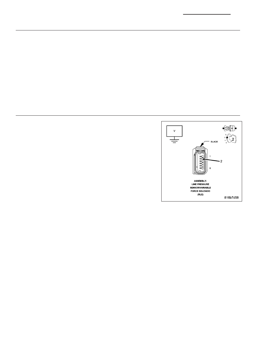
6.
CHECK THE (F856) 5-VOLT SUPPLY CIRCUIT FOR A SHORT TO VOLTAGE
Disconnect the Transmission Simulator, Miller tool #8333 and the Elec-
tronic Transmission Adapter kit.
Reconnect all previously disconnected connectors except the Line Pres-
sure Sensor/Variable Force Solenoid Assembly harness connector.
Ignition on, engine not running.
Measure the voltage of the (F856) 5-volt Supply circuit.
Is the voltage above 5.5 volts?
Yes
>> Repair the (F856) 5-volt Supply circuit for a short to voltage.
Perform 42RLE TRANSMISSION VERIFICATION TEST -
VER 1. (Refer to 21 - TRANSMISSION/TRANSAXLE/AU-
TOMATIC - 42RLE - STANDARD PROCEDURE)
No
>> Go To 7
21 - 152
AUTOMATIC TRANSMISSION 42RLE - ELECTRICAL DIAGNOSTICS
KJ