Jeep Liberty KJ. Manual - part 1025


  Index      Jeep     Jeep Liberty KJ - service repair manual 2006 year


Search            


Content   ..  1023  1024  1025  1026   ..


Jeep Liberty KJ. Manual - part 1025


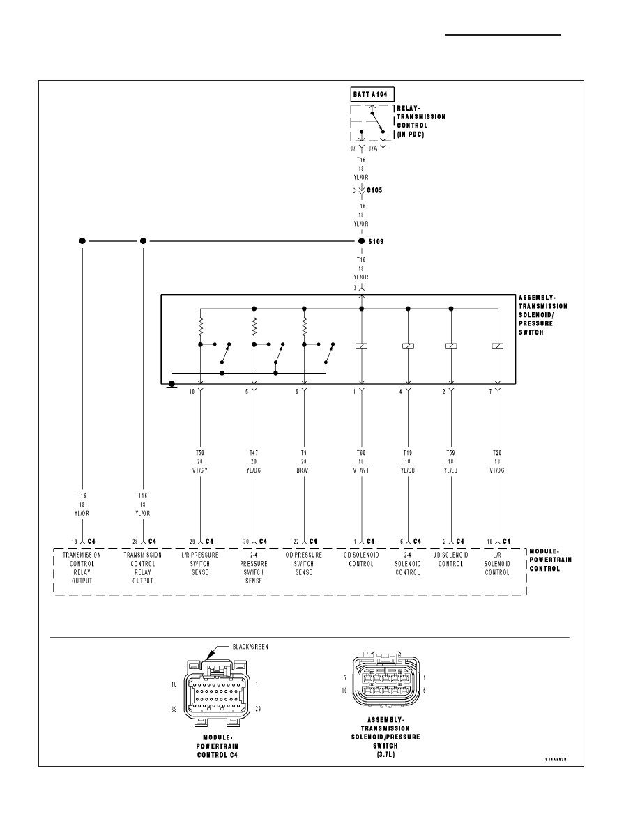
P0846-2/4 PRESSURE SWITCH RATIONALITY

For a complete wiring diagram Refer to Section 8W.

21 - 144

AUTOMATIC TRANSMISSION 42RLE - ELECTRICAL DIAGNOSTICS

KJ

When Monitored:
Whenever the engine is running.

Set Condition:
The DTC is set if one of the pressure switches are open or closed at the wrong time in a given gear. If the
problem is identified for 3 successive key starts, the transmission will go into Limp-in mode and the MIL will
turn on after 10 seconds of vehicle operation.

Possible Causes

RELATED TRANSMISSION CONTROL OUTPUT DTCS PRESENT

LOSS OF PRIME DTC PRESENT

(T47) 2/4 PRESSURE SWITCH SENSE CIRCUIT OPEN

(T47) 2/4 PRESSURE SWITCH SENSE CIRCUIT SHORT TO GROUND

(T47) 2/4 PRESSURE SWITCH SENSE CIRCUIT SHORT TO VOLTAGE

TRANSMISSION SOLENOID/PRESSURE SWITCH ASSEMBLY

POWERTRAIN CONTROL MODULE

Always perform the 42RLE Pre-Diagnostic Troubleshooting procedure before proceeding. (Refer to 21 -
TRANSMISSION/TRANSAXLE/AUTOMATIC - 42RLE - STANDARD PROCEDURE)

Theory of Operation

The Transmission system uses three pressure switches to monitor the fluid pressure in the LR, 2/4, and OD ele-
ments. The pressure switches are continuously monitored for the correct states in each gear. The 2/4 pressure
switch monitors the fluid pressure to the 2/4 clutch to confirm proper operation of the 2/4 solenoid. If the 2/4 pres-
sure switch is identified as closed in P or N, the code will immediately be set and normal operation will be allowed
for that given key start. If the problem is identified for 3 successive ignition cycles, the transmission will go into
Limp-in mode.

PRESSURE SWITCH STATES

GEAR

L/R

2/4

OD

R

OP

OP

OP

P/N

CL

OP

OP

1st

CL

OP

OP

2nd

OP

CL

OP

D

OP

OP

CL

OD

OP

CL

CL

OP = OPEN

CL = CLOSED

Diagnostic Test

1.

DETERMINING IF RELATED TRANSMISSION RELAY DTCS ARE PRESENT

With the scan tool, read Transmission DTCs

Are there any Transmission Control Relay DTCs present also?

Yes

>> Refer to the Transmission category and perform the appropriate symptom.

No

>> Go To 2

KJ

AUTOMATIC TRANSMISSION 42RLE - ELECTRICAL DIAGNOSTICS

21 - 145

2.

CHECK FOR LOSS OF PRIME DTC

With the scan tool, check for other Transmission DTCs.

Is the DTC P0944 present also?

Yes

>> Refer to the Transmission category and perform the appropriate diagnostic procedure.

No

>> Go To 3

3.

CHECK TO SEE IF P0846 IS CURRENT

With the scan tool, view DTCs.

Is the status Active for this DTC or is the STARTS SINCE SET counter 2 or less?

Yes

>> Go To 4

No

>> Go To 8

4.

PCM AND WIRING

Turn the ignition off to the lock position.

Remove the Starter Relay.

CAUTION: Removal of the Starter Relay will prevent the vehicle from being started in gear.

WARNING: The Starter Relay must be removed from the PDC. Failure to do so can result in personal injury
or death.

NOTE: Failure to remove the Starter Relay can cause a Transmission - No Response condition.
Install the Transmission Simulator, Miller tool #8333 and the Electronic Transmission Adapter kit.

Ignition on, engine not running.

With the Transmission Simulator, turn the Pressure Switch selector to 2/4.

With the scan tool , monitor the 2/4 Pressure Switch state while pressing the Pressure Switch Test button on the
Transmission Simulator.

Did the 2/4 Pressure Switch state change?

Yes

>> Replace the Transmission Solenoid/Pressure Switch Assembly per the Service Information.

Perform 42RLE TRANSMISSION VERIFICATION TEST - VER 1. (Refer to 21 - TRANSMISSION/
TRANSAXLE/AUTOMATIC - 42RLE - STANDARD PROCEDURE)

No

>> Go To 5

21 - 146

AUTOMATIC TRANSMISSION 42RLE - ELECTRICAL DIAGNOSTICS

KJ

5.

(T47) 2/4 PRESSURE SWITCH SENSE CIRCUIT OPEN

Turn the ignition off to the lock position.

Disconnect the PCM C4 harness connector.

Disconnect the Transmission Solenoid/Pressure Switch Assembly har-
ness connector.

NOTE: Check connectors - Clean/repair as necessary.

CAUTION: Do not probe the PCM harness connectors. Probing the
PCM harness connectors will damage the PCM terminals resulting
in poor terminal to pin connection. Install Miller tool #8815 to per-
form diagnosis.
Measure the resistance of the (T47) 2/4 Pressure Switch Sense circuit
from the appropriate terminal of special tool #8815 to the Transmission
Solenoid/Pressure Switch Assembly harness connector.

Is the resistance above 5.0 ohms?

Yes

>> Repair the (T47) 2/4 Pressure Switch Sense circuit for an

open.

Perform 42RLE TRANSMISSION VERIFICATION TEST -
VER 1. (Refer to 21 - TRANSMISSION/TRANSAXLE/AU-
TOMATIC - 42RLE - STANDARD PROCEDURE)

No

>> Go To 6

6.

(T47) 2/4 PRESSURE SWITCH SENSE CIRCUIT SHORT TO GROUND

Measure the resistance between ground and the (T47) 2/4 Pressure
Switch Sense circuit.

Is the resistance below 5.0 ohms?

Yes

>> Repair the (T47) 2/4 Pressure Switch Sense circuit for a

short to ground.

Perform 42RLE TRANSMISSION VERIFICATION TEST -
VER 1. (Refer to 21 - TRANSMISSION/TRANSAXLE/AU-
TOMATIC - 42RLE - STANDARD PROCEDURE)

No

>> Go To 7

KJ

AUTOMATIC TRANSMISSION 42RLE - ELECTRICAL DIAGNOSTICS

21 - 147


Content   ..  1023  1024  1025  1026   ..