Content .. 1004 1005 1006 1007 ..
Jeep Liberty KJ. Manual - part 1006
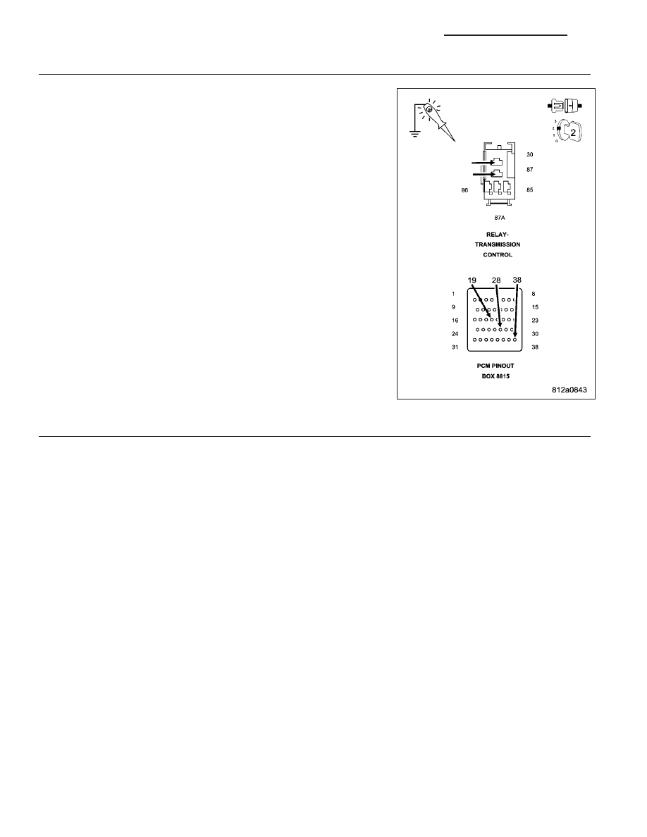
5.
CHECKING THE (T16) TRANSMISSION CONTROL RELAY OUTPUT CIRCUIT FOR AN OPEN
Turn the ignition off to the lock position.
Connect a jumper wire between (A104) Fused B+ circuit and the (T16)
Transmission Control Relay Output circuit.
Ignition on, engine not running.
Using a 12-volt test light connected to ground, check all (T16) Trans-
mission Control Relay Output circuits in the appropriate terminal of
Miller tool #8815.
Does the test light illuminate brightly?
Yes
>> Go To 6
No
>> Repair the (T16) Transmission Control Relay Output cir-
cuit(s) for an open or high resistance.
Perform 42RLE TRANSMISSION VERIFICATION TEST -
VER 1. (Refer to 21 - TRANSMISSION/TRANSAXLE/AU-
TOMATIC - 42RLE - STANDARD PROCEDURE)
6.
CHECK THE TRANSMISSION CONTROL RELAY
Turn the ignition off to the lock position.
Install a substitute Relay in place of the Transmission Control Relay.
Start the engine.
Using a voltmeter, measure the battery voltage.
With the scan tool, monitor the Transmission Switched Battery Voltage.
Compare the scan tool Transmission Switched Battery voltage to the actual battery voltage.
Is the scan tool voltage within 2.0 volts of the battery voltage?
Yes
>> Replace the Transmission Control Relay.
Perform 42RLE TRANSMISSION VERIFICATION TEST - VER 1. (Refer to 21 - TRANSMISSION/
TRANSAXLE/AUTOMATIC - 42RLE - STANDARD PROCEDURE)
No
>> Using the schematics as a guide, check the Powertrain Control Module (PCM) terminals for corrosion,
damage, or terminal push out. Pay particular attention to all power and ground circuits. Check for Ser-
vice Information Tune-ups or Service Bulletins for any possible causes that may apply. If no problems
are found, replace the PCM per the Service Information. With the scan tool, perform QUICK LEARN.
Perform 42RLE TRANSMISSION VERIFICATION TEST - VER 1. (Refer to 21 - TRANSMISSION/
TRANSAXLE/AUTOMATIC - 42RLE - STANDARD PROCEDURE)
21 - 68
AUTOMATIC TRANSMISSION 42RLE - ELECTRICAL DIAGNOSTICS
KJ