Jeep Liberty KJ. Manual - part 62


  Index      Jeep     Jeep Liberty KJ - service repair manual 2006 year


Search            


Content   ..  60  61  62  63   ..


Jeep Liberty KJ. Manual - part 62


5.

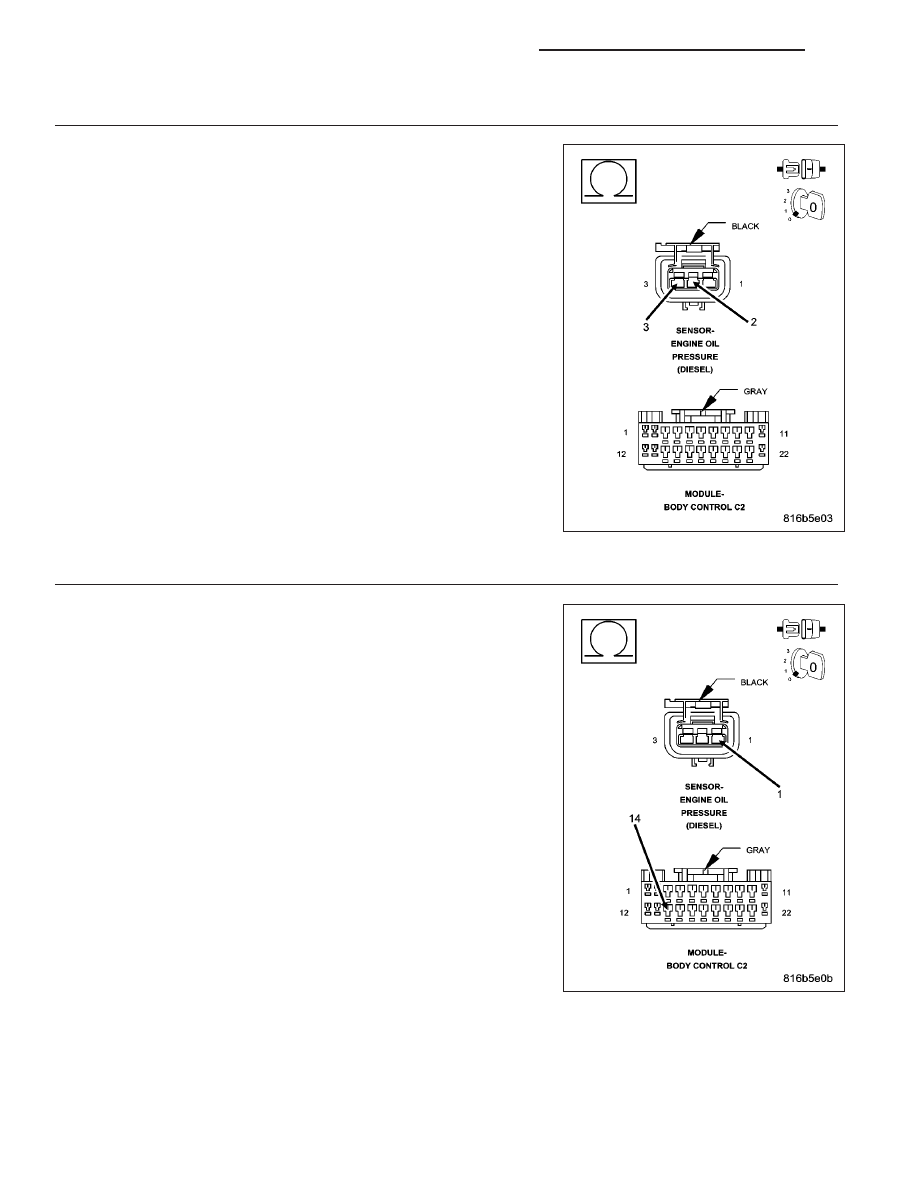
(K302) OIL PRESSURE SENSOR SIGNAL CIRCUIT SHORTED TO THE (K300) SENSOR GROUND
CIRCUIT

Measure the resistance between the (K302) Oil Pressure Sensor Signal
circuit and the (K300) Sensor ground circuit in the Oil Pressure Sensor
harness connector.

Is the resistance below 100 ohms?

Yes

>> Repair the short between the (K302) Oil Pressure Sensor

Signal circuit and the (K300) Sensor ground circuit.

Perform the BODY VERIFICATION TEST. (Refer to 8 -
ELECTRICAL/ELECTRONIC

CONTROL

MODULES

-

STANDARD PROCEDURE)

No

>> Go To 6

6.

(K301) 5-VOLT SUPPLY CIRCUIT OPEN

Turn the ignition off.

Disconnect the BCM C2 harness connector.

Measure the resistance of the (K301) 5-volt Supply circuit.

Is the resistance below 5.0 ohms?

Yes

>> Go To 7

No

>> Repair the open in the (K301) 5-volt Supply circuit.

Perform the BODY VERIFICATION TEST VER. 1 (Refer to
8 - ELECTRICAL/ELECTRONIC CONTROL MODULES -
STANDARD PROCEDURE)

8J - 54

INSTRUMENT CLUSTER - ELECTRICAL DIAGNOSTICS

KJ

7.

(K301) 5-VOLT SUPPLY CIRCUIT SHORTED TO GROUND

Measure the resistance between ground and the (K301) 5-volt Supply
circuit in the Oil Pressure Sensor harness connector.

Is the resistance below 100 ohms?

Yes

>> Repair the short to ground in the (K301) 5-volt Supply cir-

cuit.

Perform the BODY VERIFICATION TEST. (Refer to 8 -
ELECTRICAL/ELECTRONIC

CONTROL

MODULES

-

STANDARD PROCEDURE)

No

>> Go To 8

8.

BCM

NOTE: Before continuing, check the BCM harness connector terminals for corrosion, damage, or terminal
push out. Repair as necessary.
Using the schematics as a guide, inspect the wire harness and connectors. Pay particular attention to all Power and
Ground circuits.

Were there any problems found?

Yes

>> Repair as necessary.

Perform the BODY VERIFICATION TEST. (Refer to 8 - ELECTRICAL/ELECTRONIC CONTROL MOD-
ULES - STANDARD PROCEDURE)

No

>> Replace and program the BODY Control Module per Service Information.

Perform the BODY VERIFICATION TEST. (Refer to 8 - ELECTRICAL/ELECTRONIC CONTROL MOD-
ULES - STANDARD PROCEDURE)

KJ

INSTRUMENT CLUSTER - ELECTRICAL DIAGNOSTICS

8J - 55

TIRE SIZE NOT PROGRAMMED

For a complete wiring diagram Refer to Section 8W.

When Monitored:
When the battery is connected.

Set Condition:
Tire size is not programmed to a valid size. The default condition for a new BCM is un-programmed. The BCM
must be programmed with a valid tire size or the speedometer will default to Zero and this code will set.

Possible Causes

PROGRAM TIRE SIZE

Diagnostic Test

1.

PROGRAM TIRE SIZE

With the scan toolin Body Computer, select Miscellaneous, then select Program Tire Size.

Program the appropriate tire size.

With the scan tool, erase DTCs.

Turn the ignition off, wait 15 seconds, then turn the ignition on.

With the scan tool, read DTCs.

Did this DTC reset?

Yes

>> Replace and program the Body Control Module in accordance with the Service Information.

Perform BODY VERIFICATION TEST - VER 1. (Refer to 8 - ELECTRICAL/ELECTRONIC CONTROL
MODULES - STANDARD PROCEDURE)

No

>> Test Complete.

8J - 56

INSTRUMENT CLUSTER - ELECTRICAL DIAGNOSTICS

KJ

WATER IN FUEL SENSOR FAULTED HIGH (BCM)

For a complete wiring diagram Refer to Section 8W.

KJ

INSTRUMENT CLUSTER - ELECTRICAL DIAGNOSTICS

8J - 57


Content   ..  60  61  62  63   ..