Jeep Liberty KJ. Manual - part 56


  Index      Jeep     Jeep Liberty KJ - service repair manual 2006 year


Search            


Content   ..  54  55  56  57   ..


Jeep Liberty KJ. Manual - part 56


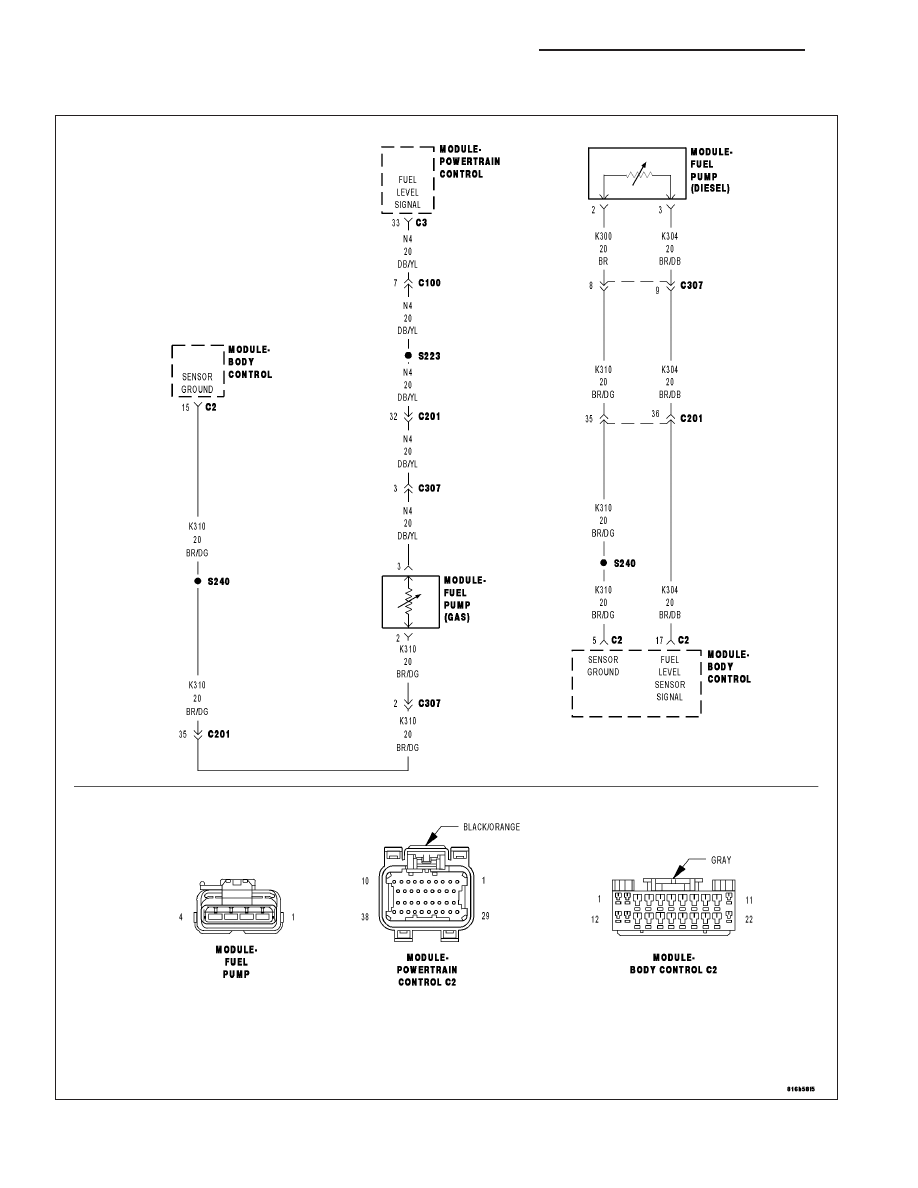
FUEL SENSOR FAULTED HIGH (BCM)

For a complete wiring diagram Refer to Section 8W

8J - 30

INSTRUMENT CLUSTER - ELECTRICAL DIAGNOSTICS

KJ

When Monitored:
Ignition on and battery voltage above 10.4 volts.

Set Condition:
The fuel level sensor signal voltage at the PCM goes above 4.9 volts for more than 90 seconds.

Possible Causes

FUEL LEVEL SENSOR VOLTAGE ABOVE 4.9 VOLTS

FUEL LEVEL SENSOR

(N4) FUEL LEVEL SIGNAL CIRCUIT SHORTED TO BATTERY VOLTAGE

(N4) FUEL LEVEL SIGNAL CIRCUIT OPEN

(K900) SENSOR GROUND CIRCUIT OPEN

PCM

Diagnostic Test

1.

FUEL LEVEL SENSOR VOLTAGE ABOVE 4.9 VOLTS

Ignition on, engine not running.

With the scan tool, read the Fuel Level Sensor voltage.

Is the Fuel Level Sensor voltage above 4.9 volts?

Yes

>> Go To 2

No

>> Refer to the INTERMITTENT CONDITION Symptom (Diagnostic Procedure).

Perform POWERTRAIN VERIFICATION TEST VER - 5. (Refer to 9 - ENGINE - STANDARD PROCE-
DURE)

2.

FUEL LEVEL SENSOR

Turn the ignition off.

Disconnect the Fuel Pump Module electrical harness connector.

Connect a jumper wire between the (N4) Fuel Level Signal circuit and the (K900) Sensor ground circuit at the Fuel
Pump Module harness connector.

Ignition on, engine not running.

With the scan tool, read the Fuel Level Sensor voltage.

NOTE: Remove the jumper wire before continuing.

Did the Fuel Level Sensor voltage change from above 4.8 volts to below 0.4 of a volt?

Yes

>> Replace the Fuel Level Sensor.

Perform POWERTRAIN VERIFICATION TEST VER - 5. (Refer to 9 - ENGINE - STANDARD PROCE-
DURE)

No

>> Go To 3

3.

DETERMINE VEHICLE ENGINE TYPE

What type of engine is the vehicle equipped with?

Gas

>> Go To 4

Gas (ESP)

Go To 8

Diesel

Go To 12

KJ

INSTRUMENT CLUSTER - ELECTRICAL DIAGNOSTICS

8J - 31

4.

(N4) FUEL LEVEL SIGNAL CIRCUIT SHORTED TO VOLTAGE

Turn the ignition off.

Disconnect the C2 and C3 PCM harness connectors.

WARNING: When the engine is operating, do not stand in a direct
line with the fan. Do not put your hands near the pulleys, belts or
fan. Do not wear loose clothing.
Ignition on, engine not running.

Measure the voltage on the (N4) Fuel Level Signal circuit at the Fuel
Pump Module harness connector.

Is the voltage above 5.3 volts?

Yes

>> Repair the short to voltage in the (N4) Fuel Level Signal cir-

cuit.

Perform POWERTRAIN VERIFICATION TEST VER - 5.
(Refer to 9 - ENGINE - STANDARD PROCEDURE)

No

>> Go To 5

5.

(N4) FUEL LEVEL SIGNAL CIRCUIT OPEN

Turn the ignition off.

CAUTION: Do not probe the pcm harness connectors. Probing the
pcm harness connectors will damage the pcm terminals resulting
in poor terminal to pin connection. Install miller special tool #8815
to perform diagnosis.
Measure the resistance of the (N4) Fuel Level Signal circuit from the
Fuel Pump Module harness connector to the appropriate terminal in
Miller Special Tool #8815.

Is the resistance below 5.0 ohms?

Yes

>> Go To 6

No

>> Repair the open in the (N4) Fuel Level Signal circuit.

Perform POWERTRAIN VERIFICATION TEST VER - 5.
(Refer to 9 - ENGINE - STANDARD PROCEDURE)

8J - 32

INSTRUMENT CLUSTER - ELECTRICAL DIAGNOSTICS

KJ

6.

(K900) SENSOR GROUND CIRCUIT OPEN

CAUTION: Do not probe the pcm harness connectors. Probing the
pcm harness connectors will damage the pcm terminals resulting
in poor terminal to pin connection. Install Miller Special Tool #8815
to perform diagnosis.
Measure the resistance of the (K900) Sensor ground circuit from the
Fuel Pump Module harness connector to the appropriate terminal of
special tool #8815.

Is the resistance below 5.0 ohms?

Yes

>> Go To 7

No

>> Repair the open in the (K900) Sensor ground circuit.

Perform POWERTRAIN VERIFICATION TEST VER - 5.
(Refer to 9 - ENGINE - STANDARD PROCEDURE)

7.

PCM

NOTE: Before continuing, check the PCM harness connector terminals for corrosion, damage, or terminal
push out. Repair as necessary.
Using the schematics as a guide, inspect the wire harness and connectors. Pay particular attention to all Power and
Ground circuits.

If there are no possible causes remaining, view repair.

Repair

Replace and program the Powertrain Control Module per Service Information.

Perform POWERTRAIN VERIFICATION TEST VER - 5. (Refer to 9 - ENGINE - STANDARD PROCE-
DURE)

KJ

INSTRUMENT CLUSTER - ELECTRICAL DIAGNOSTICS

8J - 33


Content   ..  54  55  56  57   ..