Jeep Liberty KJ. Manual - part 31


  Index      Jeep     Jeep Liberty KJ - service repair manual 2006 year


Search            


Content   ..  29  30  31  32   ..


Jeep Liberty KJ. Manual - part 31


2. Connect battery cable solenoid terminal wire har-

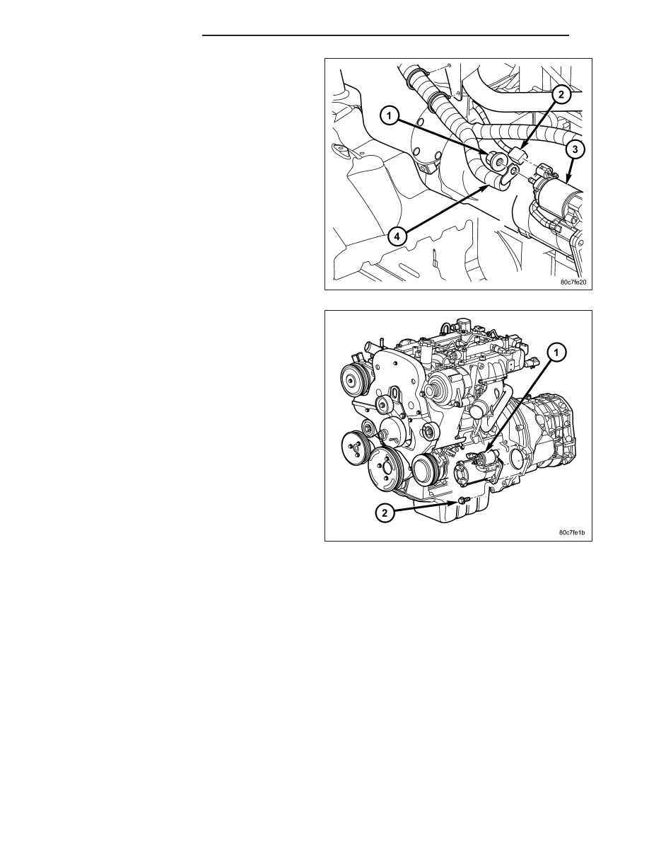
ness connector (2) to connector receptacle on
starter solenoid. Always support starter motor dur-
ing this process. Do not let starter motor hang from
wire harness.

3. Install battery cable eyelet terminal (4) onto sole-

noid B (+) terminal stud.

4. Install nut (1) securing battery cable eyelet terminal

to starter solenoid B (+) terminal stud and tighten
to 11 N·m (100 in. lbs.).

5. Position starter motor and install three bolts (2).

Tighten 3 bolts in this sequence: top bolt, bottom
bolt, middle bolt to 27 N·m (20 ft. lbs.).

6. Lower vehicle.

7. Connect negative battery cable.

3.7L

1. Position front of starter towards rear of vehicle with solenoid position rotated until it is located below starter.

Install starter by passing it between exhaust pipe and transmission bellhousing.

8F - 62

STARTING SYSTEM

KJ

2. Position starter into bellhousing and install two

bolts (2) and tighten to 54 N·m (40 ft. lbs.).

3. Install battery cable and nut to stud on starter sole-

noid and tighten to 11 N·m (100 in. lbs.).

4. Install solenoid wire connector to solenoid terminal.

5. Position starter heat shield and install nut at front

of starter.

6. Install 2 starter heat shield bolts at side of starter.

7. Install front propeller shaft.

8. Install 2 flange bolts securing left exhaust down-

pipe to crossover pipe.

9. Lower vehicle.

10. Connect negative battery cable.

KJ

STARTING SYSTEM

8F - 63

RELAY - STARTER MOTOR

DESCRIPTION

The starter relay is an electromechanical device that switches battery current to the pull-in coil of the starter sole-
noid when ignition switch is turned to Start position. The starter relay is located in the Power Distribution Center
(PDC) in the engine compartment. See PDC cover for relay identification and location.

The starter relay is a International Standards Organization (ISO) relay. Relays conforming to ISO specifications have
common physical dimensions, current capacities, terminal patterns, and terminal functions.

The starter relay cannot be repaired or adjusted and, if faulty or damaged, it must be replaced.

OPERATION

The ISO relay consists of an electromagnetic coil, a resistor or diode, and three (two fixed and one movable) elec-
trical contacts. The movable (common feed) relay contact is held against one of the fixed contacts (normally closed)
by spring pressure. When electromagnetic coil is energized, it draws the movable contact away from normally
closed fixed contact, and holds it against the other (normally open) fixed contact.

When electromagnetic coil is de-energized, spring pressure returns movable contact to normally closed position.
The resistor or diode is connected in parallel with electromagnetic coil within relay, and helps to dissipate voltage
spikes produced when coil is de-energized.

REMOVAL

The starter relay is located in the Power Distribution
Center (PDC) (2). Refer to label on PDC cover for
relay location.

1. Remove PDC cover (3).

2. Remove relay from PDC.

3. Check condition of relay terminals and PDC con-

nector terminals for damage or corrosion. Repair if
necessary before installing relay.

4. Check for pin height (pin height should be the

same for all terminals within the PDC connector).
Repair if necessary before installing relay.

INSTALLATION

1. Refer to Power Distribution Center (PDC) cover for starter relay location.

2. Install relay to PDC.

3. Install cover to PDC.

8F - 64

STARTING SYSTEM

KJ


Content   ..  29  30  31  32   ..