Jeep Liberty KJ. Manual - part 26


  Index      Jeep     Jeep Liberty KJ - service repair manual 2006 year


Search            


Content   ..  24  25  26  27   ..


Jeep Liberty KJ. Manual - part 26


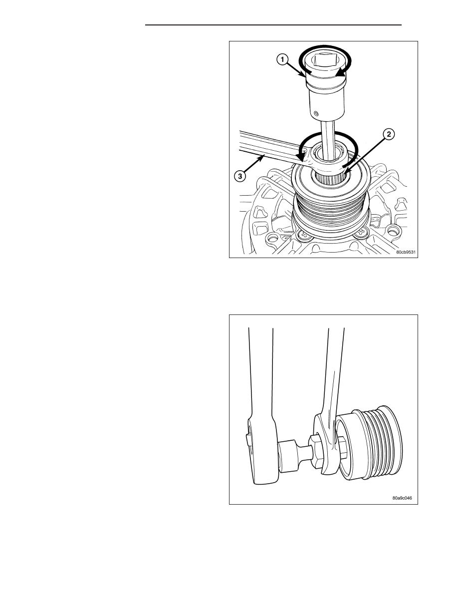
9. rotate end of tool (1) clockwise.

10. After breaking loose with tool, unthread decoupler

by hand from generator.

Litens Decoupler

1. Disconnect negative battery cable.

2. Remove generator and accessory drive belt. Refer to Generator Removal.

3. Position Special Tool #8433 into decoupler. Align to

hex end of generator shaft.

8F - 42

CHARGING SYSTEM

KJ

4. The generator shaft uses conventional right-hand

threads to attach decoupler. To break decoupler
loose from generator threads, rotate end of tool
clockwise.

5. After breaking loose with tool, unthread decoupler

by hand from generator.

INSTALLATION

INA Decoupler

1. Thread decoupler pulley onto generator shaft by hand (right-hand threads).

2. Position Special Tool #8823 (VM.1048) into decoupler.

3. Determine if end of generator shaft is hex shaped

or is splined. If hex is used, insert a 10MM deep
socket (1) into tool #8823 (VM.1048) or..............

KJ

CHARGING SYSTEM

8F - 43

4. ............if splined, insert a 5/16” 6-point hex driver

(1), or a 10MM 12-point triple square driver into
tool #8823 (VM.1048).

5. Do not use an adjustable, ratcheting “click type” torque wrench. Most “click type” wrenches will only

allow torque to be applied in a clockwise rotation. Use a dial-type or beam-type wrench. Tighten in coun-
terclockwise rotation and tighten to 110 N·m (81 ft. lbs.).

6. Install accessory drive belt, and generator. Refer to Generator Installation.

7. Connect negative battery cable.

Litens Decoupler

1. Thread decoupler pulley onto generator shaft by hand (right-hand threads).

2. Position Special Tool 8433 into decoupler. Align tool to hex end of generator shaft.

3. Do not use an adjustable, ratcheting “click

type”

torque

wrench.

Most

“click

type”

wrenches will only allow torque to be applied in
a clockwise rotation. Use a dial-type or beam-
type wrench. 
Tighten in counterclockwise rotation
and tighten to 110 N·m (81 ft. lbs.).

4. Install accessory drive belt, and generator. Refer to Generator Installation.

5. Connect negative battery cable.

8F - 44

CHARGING SYSTEM

KJ

REGULATOR - VOLTAGE

DESCRIPTION

The Electronic Voltage Regulator (EVR) is not a separate component. It is actually a voltage regulating circuit
located within the Powertrain Control Module (PCM). The EVR is not serviced separately. If replacement is neces-
sary, the PCM must be replaced.

OPERATION

The amount of DC current produced by the generator is controlled by EVR circuitry contained within the Powertrain
Control Module (PCM). This circuitry is connected in series with the generators second rotor field terminal and its
ground.

Voltage is regulated by cycling the ground path to control the strength of the rotor magnetic field. The EVR circuitry
monitors system line voltage (B+) and battery temperature (refer to Battery Temperature Sensor for more informa-
tion). It then determines a target charging voltage. If sensed battery voltage is 0.5 volts or lower than the target
voltage, the PCM grounds the field winding until sensed battery voltage is 0.5 volts above target voltage. A circuit in
the PCM cycles the ground side of the generator field up to 100 times per second (100Hz), but has the capability
to ground the field control wire 100% of the time (full field) to achieve the target voltage. If the charging rate cannot
be monitored (limp-in), a duty cycle of 25% is used by the PCM in order to have some generator output. Also refer
to Charging Operation for additional information.

KJ

CHARGING SYSTEM

8F - 45


Content   ..  24  25  26  27   ..