Jeep Liberty KJ. Manual - part 24


  Index      Jeep     Jeep Liberty KJ - service repair manual 2006 year


Search            


Content   ..  22  23  24  25   ..


Jeep Liberty KJ. Manual - part 24


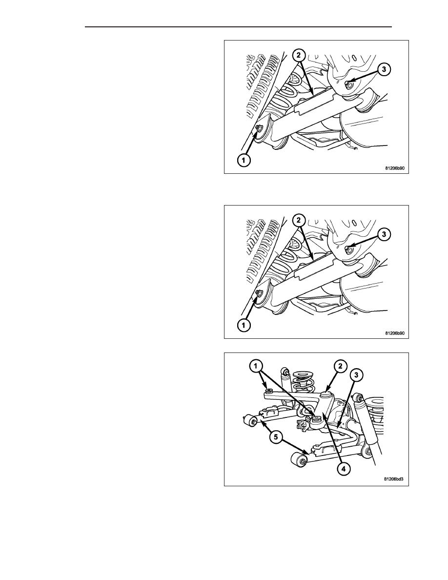
3. Remove the lower suspension arm nut and bolt (1)

from the axle bracket (1).

NOTE: When removing the right side suspension
arm from the frame rail it will be necessary to pry
the exhaust over slightly to allow enough clear-
ance to remove the bolt.

4. Remove the nut and bolt (3) from the frame rail (3)

and remove the lower suspension arm (2).

INSTALLATION

1. Position the lower suspension arm (2) in the axle

bracket and frame rail bracket (3).

NOTE: The end of the arm with the voided round
bushing attaches to the axle bracket.

2. Install the axle bracket bolt (1) and nut finger tight.

NOTE: When installing the right side suspension
arm to the frame rail it will be necessary to pry the
exhaust over slightly to allow enough clearance to
install the bolt.

3. Install the frame rail bracket bolt (3) and nut finger

tight.

4. Install the stabilizer bar (3) retaining bolts to the

suspension arm (5).

5. Remove the supports and lower the vehicle.

6. With the vehicle on the ground tighten the nut at

the frame to 163 N·m (120 ft. lbs.). Tighten the nut
at the axle bracket to 163 N·m (120 ft. lbs.).

2 - 46

REAR

KJ

DIFFERENTIAL & DRIVELINE

TABLE OF CONTENTS

page

page

PROPELLER SHAFT

. . . . . . . . . . . . . . . . . . . . . . 1

HALF SHAFT

. . . . . . . . . . . . . . . . . . . . . . . . . . . 17

FRONT AXLE - 186FIA

. . . . . . . . . . . . . . . . . . . . 30

REAR AXLE - 8 1/4

. . . . . . . . . . . . . . . . . . . . . . . 72

PROPELLER SHAFT

TABLE OF CONTENTS

page

page

PROPELLER SHAFT

DIAGNOSIS AND TESTING

PROPELLER SHAFT . . . . . . . . . . . . . . . . . . . . . . . . . 2

STANDARD PROCEDURE

PROPELLER SHAFT ANGLE . . . . . . . . . . . . . . . . . . 4

SPECIFICATIONS

PROPELLER SHAFT . . . . . . . . . . . . . . . . . . . . . . . . . 5

SPECIAL TOOLS . . . . . . . . . . . . . . . . . . . . . . . . . . . . . . . 8

SHAFT-PROPELLER FRONT

REMOVAL

REMOVAL – 2.8L DIESEL . . . . . . . . . . . . . . . . . . . . . 9

REMOVAL - 3.7L GAS ENGINE . . . . . . . . . . . . . . . . 9

INSTALLATION

INSTALLATION – 2.8L DIESEL . . . . . . . . . . . . . . . 10
INSTALLATION - 3.7L GAS ENGINE . . . . . . . . . . 10

SHAFT-PROPELLER REAR

REMOVAL . . . . . . . . . . . . . . . . . . . . . . . . . . . . . . . . . . . . 11
INSTALLATION . . . . . . . . . . . . . . . . . . . . . . . . . . . . . . . 12

UNIVERSAL JOINT-SINGLE CARDAN

DISASSEMBLY - WITH SNAP RINGS . . . . . . . . . . . 14
ASSEMBLY - WITH SNAP RINGS . . . . . . . . . . . . . . . 15

KJ

DIFFERENTIAL & DRIVELINE

3 - 1

PROPELLER SHAFT

DIAGNOSIS AND TESTING

PROPELLER SHAFT

PROPELLER SHAFT VIBRATION

DRIVELINE VIBRATION

Drive Condition

Possible Cause

Correction

Propeller Shaft Noise

1. Undercoating or other foreign
material on shaft.

1. Clean exterior of shaft and wash
with solvent.

2. Loose U-joint clamp screws.

2. Install new clamps and screws
and tighten to proper torque.

3. Loose or bent U-joint yoke or
excessive runout.

3. Install new yoke.

4. Incorrect driveline angularity.

4. Measure and correct driveline
angles.

5. Worn joint.

5. Install new joint.

6. Propeller shaft damaged or out
of balance.

6. Installl new propeller shaft.

7. Broken rear spring.

7. Install new rear spring.

8. Excessive runout or unbalanced
condition.

8. Re-index propeller shaft, test, and
evaluate.

9. Excessive drive pinion gear shaft
runout.

9. Re-index propeller shaft and
evaluate.

10. Excessive axle yoke deflection.

10. Inspect and replace yoke if
necessary.

11. Excessive transfer case runout.

11. Inspect and repair as necessary.

U-Joint Noise

1. Loose U-joint clamp screws.

1. Install new clamps and screws
and tighten to proper torque.

2. Lack of lubrication.

2. Replace joints as necessary.

Out-of-round tire or wheels that are out of balance, will cause a low frequency vibration.

Brake rotors that are unbalanced will cause a harsh, low frequency vibration.

Driveline vibration can be caused by loose or damaged engine mounts.

Propeller shaft vibration increases with vehicle speed. A vibration that occurs at a specific speed is not usually
caused by a out of balance propeller shaft. Worn universal joints or an incorrect propeller shaft angle, can cause
such a vibration.

3 - 2

PROPELLER SHAFT

KJ

BALANCE

NOTE: Indexing the propeller shaft 180° relative to
the yoke may eliminate some vibrations.

1. Raise the vehicle.

2. Clean all the foreign material from the propeller

shaft and universal joints.

3. Inspect propeller shaft for missing balance weights,

broken welds, and bent areas.

NOTE: If the propeller shaft is bent, it must be
replaced.

4. Inspect universal joints for wear, properly installa-

tion and correct alignment with the shaft.

5. Remove wheels and tires and install wheel lug nuts

to retain brake drums/rotors.

6. Mark and number the shaft six inches from the pinion yoke end at four positions 90 degrees apart.

7. Run and accelerate the vehicle until vibration occurs. Note the intensity and speed the vibration occurred. Stop

the engine.

8. Position one screw clamp (1) on the propeller shaft with a screw driver (2).

9. Start the engine and check for vibration. If there is little or no change in vibration, move the clamp to the next

positions. Repeat the vibration test. If there is no difference in vibration at the other positions, the source of the
vibration may not be propeller shaft.

10. If vibration decreased, install a second clamp and

repeat the test.

11. If the additional clamp causes an additional vibra-

tion, separate the clamps (1) (1/4 inch above and
below the mark). Repeat the vibration test.

12. Increase distance between the clamps and repeat

the test until the amount of vibration is at the low-
est level. Bend the slack end of the clamps so the
screws will not loosen.

13. If vibration remains unacceptable, repeat the pro-

cedure to the front end of the propeller shaft.

14. Install wheel and tires, and lower vehicle.

KJ

PROPELLER SHAFT

3 - 3


Content   ..  22  23  24  25   ..