Jeep Grand Cherokee WK. Manual - part 990
P0509-IDLE AIR CONTROL VALVE SENSE CIRCUIT HIGH (CONTINUED)
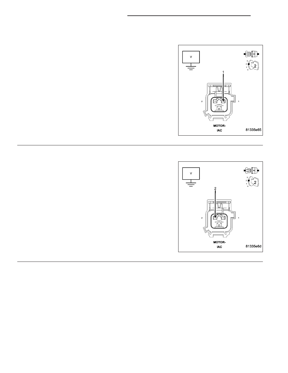
3.
(K961) IAC SIGNAL CIRCUIT SHORTED TO BATTERY VOLTAGE
Turn the ignition off.
Disconnect the C2 PCM harness connector.
Ignition on, engine not running.
Measure the voltage on the (K961) IAC Signal circuit in the IAC Motor
harness connector.
Is the voltage above 0.5 of a volt?
Yes
>> Repair the short to battery voltage in the (K961) IAC Sig-
nal circuit.
Perform the POWERTRAIN VERIFICATION TEST. (Refer
to 9 - ENGINE - STANDARD PROCEDURE)
No
>> Go To 4
4.
(K61) IAC CONTROL CIRCUIT SHORTED TO BATTERY VOLTAGE
Measure the voltage on the (K61) IAC Control circuit in the IAC Motor
harness connector.
Is the voltage above 0.5 of a volt?
Yes
>> Repair the short to battery voltage in the (K61) IAC Con-
trol circuit.
Perform the POWERTRAIN VERIFICATION TEST. (Refer
to 9 - ENGINE - STANDARD PROCEDURE)
No
>> Go To 5
9 - 556
ENGINE ELECTRICAL DIAGNOSTICS
WK