Jeep Grand Cherokee WK. Manual - part 941


  Index      Jeep     Jeep Grand Cherokee WK - service repair manual 2005 year


Search            


Content   ..  939  940  941  942   ..


Jeep Grand Cherokee WK. Manual - part 941


P0304-CYLINDER 4 MISFIRE (CONTINUED)
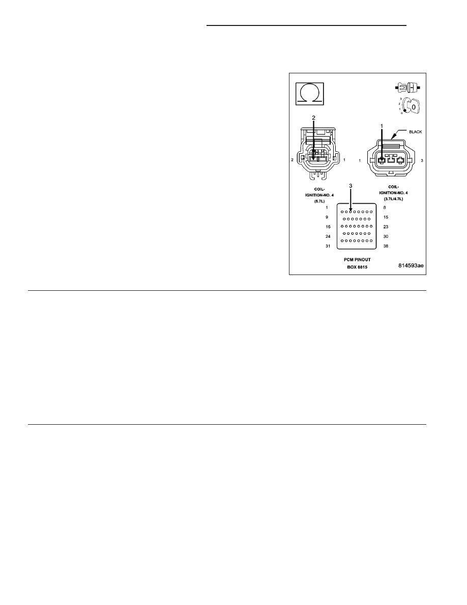
16.

(K15) COIL CONTROL NO.4 CIRCUIT

Turn the ignition off.

Disconnect the C2 PCM harness connector.

CAUTION: Do not probe the PCM harness connectors. Probing
the PCM harness connectors will damage the PCM terminals
resulting in poor terminal to pin connection. Install Miller Special
Tool #8815 to perform diagnosis.
Check the (K15) Coil Control No.4 circuit for an open, short to ground,
and short to voltage.

Was a problem found with the (K15) Coil Control No.4 circuit?

Yes

>> Repair the (K15) Coil Control No.4 circuit.

Perform the POWERTRAIN VERIFICATION TEST. (Refer
to 9 - ENGINE - STANDARD PROCEDURE)

No

>> Go To 17

17.

PCM

NOTE: Before continuing, check the PCM harness connector terminals for corrosion, damage, or terminal
push out. Repair as necessary.
Using the schematics as a guide, inspect the wire harness and connectors. Pay particular attention to all Power and
Ground circuits.

Were there any problems found?

Yes

>> Repair as necessary.

Perform the POWERTRAIN VERIFICATION TEST. (Refer to 9 - ENGINE - STANDARD PROCEDURE)

No

>> Replace and program the Powertrain Control Module per Service Information.

Perform the POWERTRAIN VERIFICATION TEST. (Refer to 9 - ENGINE - STANDARD PROCEDURE)

9 - 360

ENGINE ELECTRICAL DIAGNOSTICS

WK

P0305-CYLINDER 5 MISFIRE

WK

ENGINE ELECTRICAL DIAGNOSTICS

9 - 361

P0305-CYLINDER 5 MISFIRE (CONTINUED)

For the Engine circuit diagram (Refer to 9 - ENGINE - SCHEMATICS AND DIAGRAMS).

For a complete wiring diagram Refer to Section 8W.

When Monitored:
Any time the engine is running, and the adaptive numerator has been successfully updated.

Set Condition:
When more than 2% (2.5% LEV) misfire rate is measured during two trips, or with 10% to 30% misfire rate
during on trip. Three good trips to clear the MIL.

Possible Causes

(F42), (A15) ASD RELAY OUTPUT CIRCUIT

(K38) INJECTOR CONTROL NO.5 CIRCUIT

(K16) COIL CONTROL NO.5 CIRCUIT

IGNITION WIRE

SPARK PLUG

IGNITION COIL

FUEL PUMP INLET STRAINER PLUGGED

RESTRICTED FUEL SUPPLY LINE

FUEL PUMP MODULE

FUEL PRESSURE LEAK DOWN

FUEL INJECTOR

ENGINE MECHANICAL

PCM

Always perform the Pre-Diagnostic Troubleshooting procedure before proceeding. (Refer to 9 - ENGINE -
DIAGNOSIS AND TESTING).

Diagnostic Test

1.

CYLINDER MIS-FIRE CONDITION ACTIVE

Engine running.

Observe the WHICH CYLINDER IS MISFIRING screen for at least one minute with a scan tool.

Is there a misfire present at this time?

Yes

>> Go To 2

No

>> Refer to the INTERMITTENT CONDITION Diagnostic Procedure.

Perform the POWERTRAIN VERIFICATION TEST. (Refer to 9 - ENGINE - STANDARD PROCEDURE)

9 - 362

ENGINE ELECTRICAL DIAGNOSTICS

WK

P0305-CYLINDER 5 MISFIRE (CONTINUED)

2.

VISUAL INSPECTION

NOTE: Anything that affects the speed of the crankshaft can cause a misfire DTC.

NOTE: When a Misfire is detected for a particular cylinder, the PCM will shut down that cylinders Injector
Control circuit.
- Visually inspect the engine for any of the following conditions.

- Worn serpentine belt

- Binding Engine-Driven accessories: A/C Compressor, P/S Pump, Water pump.

- Misalignment of the Water pump, P/S Pump and A/C Compressor pulleys

- Corroded PCM power and ground circuits.

- Improper CKP, CMP, MAP, and TP Sensor mounting

- Poor connector/terminal to component connection. i.e., CKP sensor, Fuel Injector, Ign coil, etc.

- Vacuum leaks

- Restricted Air Induction system or Exhaust system.

- Internal engine component failures.

Were any of the above conditions present?

Yes

>> Repair as necessary.

Perform the POWERTRAIN VERIFICATION TEST. (Refer to 9 - ENGINE - STANDARD PROCEDURE)

No

>> Go To 3

WK

ENGINE ELECTRICAL DIAGNOSTICS

9 - 363


Content   ..  939  940  941  942   ..