Jeep Grand Cherokee WK. Manual - part 897
P0139-O2 SENSOR 1/2 SLOW RESPONSE (CONTINUED)
3.
(K141) O2 1/2 SIGNAL CIRCUIT
Turn the ignition off
Disconnect the 1/2 O2 Sensor harness connector.
Ignition on, engine not running.
Measure the voltage on the (K141) O2 1/2 Signal circuit in the O2
Sensor harness connector.
Is the voltage between 4.5 and 5.0 volts?
Yes
>> Go To 4
No
>> Check the (K141) O2 1/2 Signal circuit for a short to
ground, open, or short to voltage. If OK, replace and pro-
gram the Powertrain Control Module per Service Informa-
tion.
Perform the POWERTRAIN VERIFICATION TEST. (Refer
to 9 - ENGINE - STANDARD PROCEDURE)
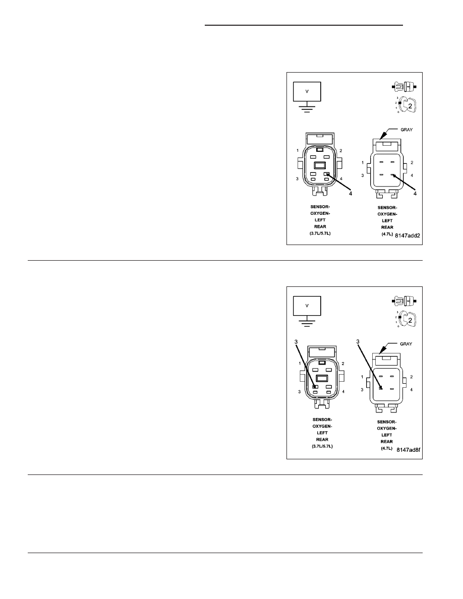
4.
(K904) O2 RETURN DOWNSTREAM CIRCUIT
Measure the voltage on the (K904) O2 Return Downstream circuit in
the 1/2 O2 Sensor harness connector.
Is the voltage at 2.5 volts?
Yes
>> Go To 5
No
>> Check the (K904) O2 Return Downstream circuit for a
short to ground, open, or short to voltage. If OK, replace
and program the Powertrain Control Module per Service
Information.
Perform the POWERTRAIN VERIFICATION TEST. (Refer
to 9 - ENGINE - STANDARD PROCEDURE)
5.
O2 SENSOR
If there are no possible causes remaining, view repair.
Repair
Replace the O2 Sensor
Perform the POWERTRAIN VERIFICATION TEST. (Refer to 9 - ENGINE - STANDARD PROCEDURE)
9 - 184
ENGINE ELECTRICAL DIAGNOSTICS
WK