Jeep Grand Cherokee WK. Manual - part 880
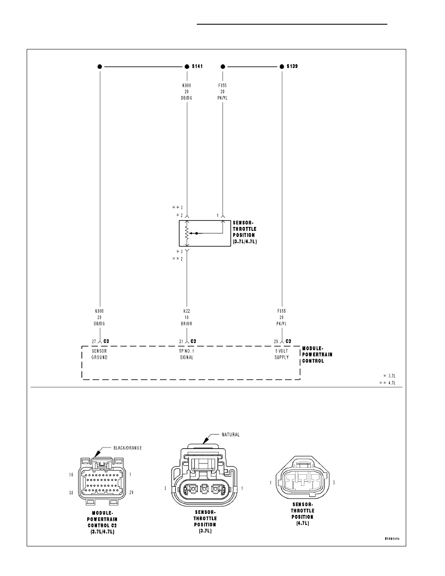
P0122-THROTTLE POSITION SENSOR 1 CIRCUIT LOW (3.7L, 4.7L)
9 - 116
ENGINE ELECTRICAL DIAGNOSTICS
WK
|
|
|
P0122-THROTTLE POSITION SENSOR 1 CIRCUIT LOW (3.7L, 4.7L) 9 - 116 ENGINE ELECTRICAL DIAGNOSTICS WK |