Jeep Grand Cherokee WK. Manual - part 879


  Index      Jeep     Jeep Grand Cherokee WK - service repair manual 2005 year


Search            


Content   ..  877  878  879  880   ..


Jeep Grand Cherokee WK. Manual - part 879


P0121-THROTTLE POSITION SENSOR 1 PERFORMANCE (CONTINUED)

5.

(K22) TP SENSOR NO.1 SIGNAL CIRCUIT OR (K122) TP SENSOR NO.2 SIGNAL CIRCUIT SHORTED TO
GROUND

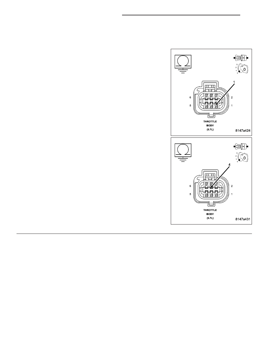
Measure the resistance between ground and the (K22) TP Sensor
No.1 Signal circuit and the (K122) TP Sensor No.2 Signal circuit in
Throttle Body harness connector.

Is the resistance below 100 ohms?

Yes

>> Repair the short to ground in the (K22) TP Sensor No.1

Signal circuit or the (K122) TP Sensor No.2 Signal circuit.

Perform the POWERTRAIN VERIFICATION TEST. (Refer
to 9 - ENGINE - STANDARD PROCEDURE)

No

>> Go To 6

9 - 112

ENGINE ELECTRICAL DIAGNOSTICS

WK

P0121-THROTTLE POSITION SENSOR 1 PERFORMANCE (CONTINUED)

6.

EXCESSIVE RESISTANCE IN THE (F855) 5–VOLT SUPPLY CIRCUIT

Measure the resistance of the (F855) 5-volt Supply circuit from the
Throttle Body harness connector to the appropriate terminal of special
tool #8815.

Is the resistance below 5.0 ohms?

Yes

>> Go To 7

No

>> Repair the excessive resistance in the (F855) 5-volt Sup-

ply circuit.

Perform the POWERTRAIN VERIFICATION TEST. (Refer
to 9 - ENGINE - STANDARD PROCEDURE)

7.

(F855) 5-VOLT SUPPLY SHORTED TO GROUND

Measure the resistance between ground and the (F855) 5-volt Supply
circuit in the Throttle Body harness connector.

Is the resistance below 100 ohms?

Yes

>> Repair the short to ground in the (F855) 5-volt Supply cir-

cuit.

Perform the POWERTRAIN VERIFICATION TEST. (Refer
to 9 - ENGINE - STANDARD PROCEDURE)

No

>> Go To 8

WK

ENGINE ELECTRICAL DIAGNOSTICS

9 - 113

P0121-THROTTLE POSITION SENSOR 1 PERFORMANCE (CONTINUED)

8.

EXCESSIVE RESISTANCE IN THE (K922) SENSOR RETURN CIRCUIT

Measure the resistance of the (K922) Sensor Return circuit from the
Throttle Body harness connector to the appropriate terminal of special
tool #8815.

Is the resistance below 5.0 ohms?

Yes

>> Go To 9

No

>> Repair the excessive resistance in the (K922) Sensor

Return circuit.

Perform the POWERTRAIN VERIFICATION TEST. (Refer
to 9 - ENGINE - STANDARD PROCEDURE)

9.

(K22) TP SENSOR NO.1 SIGNAL CIRCUIT SHORTED TO THE (K122) TP SENSOR NO.2 SIGNAL CIRCUIT

Measure the resistance between the (K22) TP Sensor No.1 Signal cir-
cuit and the (K122) TP Sensor No.2 Signal circuit in the Throttle Body
harness connector.

Is the resistance below 5.0 ohms?

Yes

>> Repair the short between the (K122) TP Sensor No.2 Sig-

nal circuit and the (K22) TP Sensor No.1 Signal circuit.

Perform the POWERTRAIN VERIFICATION TEST. (Refer
to 9 - ENGINE - STANDARD PROCEDURE)

No

>> Go To 10

9 - 114

ENGINE ELECTRICAL DIAGNOSTICS

WK

P0121-THROTTLE POSITION SENSOR 1 PERFORMANCE (CONTINUED)

10.

PCM

NOTE: Before continuing, check the PCM harness connector terminals for corrosion, damage, or terminal
push out. Repair as necessary.
Using the schematics as a guide, inspect the wire harness and connectors. Pay particular attention to all Power and
Ground circuits.

Were there any problems found?

Yes

>> Repair as necessary.

Perform the POWERTRAIN VERIFICATION TEST. (Refer to 9 - ENGINE - STANDARD PROCEDURE)

No

>> Replace and program the Powertrain Control Module per Service Information.

Perform the POWERTRAIN VERIFICATION TEST. (Refer to 9 - ENGINE - STANDARD PROCEDURE)

11.

THROTTLE FOLLOWER TEST

Ignition on, engine not running.

With a scan tool, perform the Throttle Follower Test and monitor the TP Sensor No.1 or No.2 voltage.

Slowly press the throttle pedal down.

The voltage for TP Sensor No.1 should start at approximately 0.3 of a volt and increase to above 4.7 volts.

The voltage for TP Sensor No.2 should start at approximately 4.7 volts and decrease to approximately 0.3 of a volt.

Is the voltage within the range of the listed specification for the appropriate Sensor?

Yes

>> Refer to the INTERMITTENT CONDITION Diagnostic Procedure.

Perform the POWERTRAIN VERIFICATION TEST. (Refer to 9 - ENGINE - STANDARD PROCEDURE)

No

>> Disconnect the Battery when replacing the Throttle Body Assembly. Replace the Throttle Body Assem-

bly. After installation is complete, use a scan tool and select the ETC RELEARN function.

Perform the POWERTRAIN VERIFICATION TEST. (Refer to 9 - ENGINE - STANDARD PROCEDURE)

WK

ENGINE ELECTRICAL DIAGNOSTICS

9 - 115


Content   ..  877  878  879  880   ..