Jeep Grand Cherokee WK. Manual - part 871


  Index      Jeep     Jeep Grand Cherokee WK - service repair manual 2005 year


Search            


Content   ..  869  870  871  872   ..


Jeep Grand Cherokee WK. Manual - part 871


P0108-MANIFOLD ABSOLUTE PRESSURE SENSOR CIRCUIT HIGH (CONTINUED)

3.

(K1) MAP SIGNAL CIRCUIT SHORTED TO BATTERY VOLTAGE

Turn the ignition off.

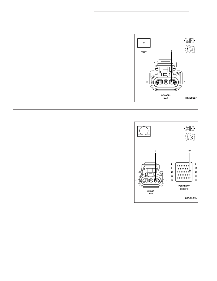
Disconnect the C1 and C2 PCM harness connectors.

Ignition on, engine not running.

Measure the voltage on the (K1) MAP Signal circuit in the MAP Sen-
sor harness connector.

Is the voltage above 5.2 volts?

Yes

>> Repair the short to battery voltage in the (K1) MAP Signal

circuit.

Perform the POWERTRAIN VERIFICATION TEST. (Refer
to 9 - ENGINE - STANDARD PROCEDURE)

No

>> Go To 4

4.

(K1) MAP SIGNAL CIRCUIT OPEN

Turn the ignition off.

CAUTION: Do not probe the PCM harness connectors. Probing
the PCM harness connectors will damage the PCM terminals
resulting in poor terminal to pin connection. Install Miller Special
Tool #8815 to perform diagnosis.
Measure the resistance of the (K1) MAP Signal circuit from the MAP
Sensor harness connector to the appropriate terminal of special tool
#8815.

Is the resistance below 5.0 ohms?

Yes

>> Go To 5

No

>> Repair the open in the (K1) MAP Signal circuit.

Perform the POWERTRAIN VERIFICATION TEST. (Refer
to 9 - ENGINE - STANDARD PROCEDURE)

9 - 80

ENGINE ELECTRICAL DIAGNOSTICS

WK

P0108-MANIFOLD ABSOLUTE PRESSURE SENSOR CIRCUIT HIGH (CONTINUED)

5.

(K1) MAP SIGNAL CIRCUIT SHORTED TO THE (F856) 5-VOLT SUPPLY CIRCUIT

Measure the resistance between the (K1) MAP Signal circuit and the
(F856) 5-volt Supply circuit in the MAP Sensor harness connector.

Is the resistance below 100 ohms?

Yes

>> Repair the short between the (F856) 5-volt Supply circuit

and the (K1) MAP Signal circuit.

Perform the POWERTRAIN VERIFICATION TEST. (Refer
to 9 - ENGINE - STANDARD PROCEDURE)

No

>> Go To 6

6.

(K900) SENSOR GROUND CIRCUIT OPEN

Measure the resistance of the (K900) Sensor ground circuit from the
MAP Sensor harness connector to the appropriate terminal of special
tool #8815.

Is the resistance below 5.0 ohms?

Yes

>> Go To 7

No

>> Repair the open in the (K900) Sensor ground circuit.

Perform the POWERTRAIN VERIFICATION TEST. (Refer
to 9 - ENGINE - STANDARD PROCEDURE)

WK

ENGINE ELECTRICAL DIAGNOSTICS

9 - 81

P0108-MANIFOLD ABSOLUTE PRESSURE SENSOR CIRCUIT HIGH (CONTINUED)

7.

PCM

NOTE: Before continuing, check the PCM harness connector terminals for corrosion, damage, or terminal
push out. Repair as necessary.
Using the schematics as a guide, inspect the wire harness and connectors. Pay particular attention to all Power and
Ground circuits.

Were there any problems found?

Yes

>> Repair as necessary.

Perform the POWERTRAIN VERIFICATION TEST. (Refer to 9 - ENGINE - STANDARD PROCEDURE)

No

>> Replace and program the Powertrain Control Module per Service Information.

Perform the POWERTRAIN VERIFICATION TEST. (Refer to 9 - ENGINE - STANDARD PROCEDURE)

9 - 82

ENGINE ELECTRICAL DIAGNOSTICS

WK

P0111-INTAKE AIR TEMPERATURE SENSOR RATIONALITY

WK

ENGINE ELECTRICAL DIAGNOSTICS

9 - 83


Content   ..  869  870  871  872   ..