Jeep Grand Cherokee WK. Manual - part 709


  Index      Jeep     Jeep Grand Cherokee WK - service repair manual 2005 year


Search            


Content   ..  707  708  709  710   ..


Jeep Grand Cherokee WK. Manual - part 709


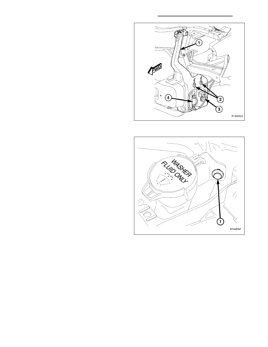
NOTE: Make sure to properly connect the washer
hoses to the windshield washer pump. Failure to
properly connect the hoses will cause the front
and rear washer systems to operate incorrectly.

4. Properly connect the two washer hoses to the

windshield washer pump on the reservoir (1).

5. Connect the wire harness connectors (2) to the

washer fluid level switch (3) and the windshield
washer pump (4).

6. Install the liner into the left front fender wheel

house.

7. Lower the vehicle.

8. Install the retainer (1) that secures the washer res-

ervoir filler neck to the upper radiator support.

9. Install the washer reservoir filler cap hinge onto the

hook on the filler neck and close the cap.

10. Refill the washer reservoir with the washer fluid

drained during removal.

11. Reconnect the battery negative cable.

8R - 58

FRONT WIPERS/WASHERS - SERVICE INFORMATION

WK

RELAY-WIPER HIGH/LOW

DESCRIPTION

The wiper high/low relay (1) is a International Stan-
dards Organization (ISO) micro relay. Relays conform-
ing to the ISO specifications have common physical
dimensions, current capacities, terminal functions and
patterns (2). This relay is contained within a small,
rectangular, molded plastic housing and is connected
to all of the required inputs and outputs through five
integral male spade-type terminals that extend from
the relay base plate.

The wiper high/low relay is located in the integrated
power module (IPM) in the engine compartment, near
the battery. Refer to the layout label on the underside
of the IPM cover for specific relay cavity assignment
information. The wiper high/low relay cannot be
adjusted or repaired and, if faulty or damaged, it must
be replaced.

OPERATION

The wiper high/low relay is an electromechanical switch that uses a low current input from the front control module
(FCM) to control a high current output to the front wiper motor. The movable common feed contact point is held
against the fixed normally closed contact point by spring pressure. When the relay coil is energized, an electromag-
netic field is produced by the coil windings. This electromagnetic field draws the movable relay contact point away
from the fixed normally closed contact point, and holds it against the fixed normally open contact point. When the
relay coil is de-energized, spring pressure returns the movable contact point back against the fixed normally closed
contact point. A resistor is connected in parallel with the relay coil in the relay, and helps to dissipate voltage spikes
and electromagnetic interference that can be generated as the electromagnetic field of the relay coil collapses.

The wiper high/low relay terminals are connected to the vehicle electrical system through a connector receptacle in
the integrated power module (IPM). The inputs and outputs of the wiper high/low relay include:

Common Feed Terminal - The common feed terminal (30) is connected to the output of the wiper on/off relay
at all times through the wiper on/off relay output circuit.

Coil Ground Terminal - The coil ground terminal (85) is connected to a control output of the FCM through a
wiper high/low relay control circuit. The FCM controls wiper motor operation by controlling a ground path
through this circuit.

Coil Battery Terminal - The coil battery terminal (86) receives battery current at all times from a fuse in the
power distribution center (PDC) through a fused ignition switch output (run-acc) circuit.

Normally Open Terminal - The normally open terminal (87) is connected to the high speed brush of the wiper
motor through a wiper high/low relay high speed output circuit, and is connected to the high speed brush
whenever the relay is energized.

Normally Closed Terminal - The normally closed terminal (87A) is connected to the low speed brush of the
wiper motor through a wiper high/low relay low speed output circuit, and is connected to the low speed brush
whenever the relay is de-energized.

The wiper high/low relay can be diagnosed using conventional diagnostic tools and methods. However, conventional
diagnostic methods may not prove conclusive in the diagnosis of the steering control module (SCM), FCM or the
electronic message inputs to or outputs from the SCM and the FCM that control the operation of the wiper high/low
relay. The most reliable, efficient, and accurate means to diagnose the wiper high/low relay, SCM, FCM or the elec-
tronic message inputs and outputs related to the wiper high/low relay operation requires the use of a diagnostic
scan tool. Refer to the appropriate diagnostic information.

WK

FRONT WIPERS/WASHERS - SERVICE INFORMATION

8R - 59

REMOVAL

1. Disconnect and isolate the negative battery cable.

2. Open the cover of the integrated power module

(IPM) (1) located in the engine compartment.

NOTE: Refer to the fuse and relay layout map on
the inside of the IPM cover for wiper high/low
relay location.

3. Remove the wiper high/low relay (2) from the IPM.

INSTALLATION

NOTE: Refer to the fuse and relay layout map on
the inside of the integrated power module (IPM)
cover for wiper high/low relay location.

1. Position the wiper high/low relay (2) into the proper

receptacle of the IPM (1) located in the engine
compartment.

2. Align the wiper high/low relay terminals with the

terminal cavities in the IPM receptacle and push
down firmly on the relay until the terminals are fully
seated.

3. Close the cover of the IPM.

4. Reconnect the negative battery cable.

8R - 60

FRONT WIPERS/WASHERS - SERVICE INFORMATION

WK

RELAY-WIPER ON/OFF

DESCRIPTION

The wiper on/off relay (1) is a International Standards
Organization (ISO) micro relay. Relays conforming to
the ISO specifications have common physical dimen-
sions, current capacities, terminal functions and pat-
terns (2). This relay is contained within a small,
rectangular, molded plastic housing and is connected
to all of the required inputs and outputs through five
integral male spade-type terminals that extend from
the relay base plate.

The wiper on/off relay is located in the intergrated
power module (IPM) in the engine compartment near
the battery. Refer to the layout label on the underside
of the IPM cover for specific relay cavity assignment
information. The wiper on/off relay cannot be adjusted
or repaired and, if faulty or damaged, it must be
replaced.

OPERATION

The wiper on/off relay is an electromechanical switch that uses a low current input from the front control module
(FCM) to control a high current output to the wiper motor. The movable common feed contact point is held against
the fixed normally closed contact point by spring pressure. When the relay coil is energized, an electromagnetic field
is produced by the coil windings. This electromagnetic field draws the movable relay contact point away from the
fixed normally closed contact point, and holds it against the fixed normally open contact point. When the relay coil
is de-energized, spring pressure returns the movable contact point back against the fixed normally closed contact
point. A resistor is connected in parallel with the relay coil in the relay, and helps to dissipate voltage spikes and
electromagnetic interference that can be generated as the electromagnetic field of the relay coil collapses.

The wiper on/off relay terminals are connected to the vehicle electrical system through a connector receptacle in the
integrated power module (IPM). The inputs and outputs of the wiper on/off relay include:

Common Feed Terminal - The common feed terminal (30) is connected to the common feed terminal of the
wiper high/low relay at all times through the wiper on/off relay output circuit.

Coil Ground Terminal - The coil ground terminal (85) is connected to a control output of the FCM through a
wiper on/off relay control circuit. The FCM controls wiper motor operation by controlling a ground path through
this circuit.

Coil Battery Terminal - The coil battery terminal (86) receives battery current at all times from a fuse in the
power distribution center (PDC) through a fused ignition switch output (run-acc) circuit.

Normally Open Terminal - The normally open terminal (87) receives battery current at all times from a fuse
in the PDC through a fused ignition switch output (run-acc) circuit, and provides battery current to the wiper
on/off relay output circuit whenever the relay is energized.

Normally Closed Terminal - The normally closed terminal (87A) is connected to ground at all times through
a take out of the headlamp and dash wire harness with an eyelet terminal connector that is secured by a
screw to the front end sheet metal, and is connected to the wiper on/off relay output circuit whenever the relay
is de-energized.

The wiper on/off relay may be diagnosed using conventional diagnostic tools and methods. However, conventional
diagnostic methods may not prove conclusive in the diagnosis of the steering control module (SCM), FCM or the
electronic message inputs to or outputs from the SCM and the FCM that control the operation of the wiper on/off
relay. The most reliable, efficient, and accurate means to diagnose the wiper on/off relay, SCM, FCM or the elec-
tronic message inputs and outputs related to the wiper on/off relay operation requires the use of a diagnostic scan
tool. Refer to the appropriate diagnostic information.

WK

FRONT WIPERS/WASHERS - SERVICE INFORMATION

8R - 61


Content   ..  707  708  709  710   ..