Jeep Grand Cherokee WK. Manual - part 662


  Index      Jeep     Jeep Grand Cherokee WK - service repair manual 2005 year


Search            


Content   ..  660  661  662  663   ..


Jeep Grand Cherokee WK. Manual - part 662


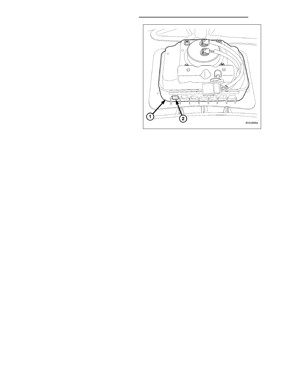
7. Disengage each of the hooks (2) of the airbag

housing from the windows in the forward and rear-
ward vertical walls of the airbag retainer (1) on the
underside of the top pad. To disengage the hooks,
use hand pressure to push the adjacent edge of
the airbag housing firmly and evenly downward into
the retainer receptacle, while at the same time pull-
ing outward on the upper edge of the receptacle
wall.

8. With all of the hooks disengaged, lift the housing,

inflator, and cushion as a unit from the retainer
receptacle on underside of the instrument panel top
pad.

INSTALLATION

WARNING: To avoid personal injury or death, on vehicles equipped with airbags, disable the supplemental
restraint system before attempting any steering wheel, steering column, airbag, seat belt tensioner, impact
sensor, or instrument panel component diagnosis or service. Disconnect and isolate the battery negative
(ground) cable, then wait two minutes for the system capacitor to discharge before performing further diag-
nosis or service. This is the only sure way to disable the supplemental restraint system. Failure to take the
proper precautions could result in accidental airbag deployment.

WARNING: To avoid personal injury or death, when removing a deployed airbag, rubber gloves, eye protec-
tion, and a long-sleeved shirt should be worn. There may be deposits on the airbag unit and other interior
surfaces. In large doses, these deposits may cause irritation to the skin and eyes.

WARNING: Use extreme care to prevent any foreign material from entering the passenger airbag, or becom-
ing entrapped between the passenger airbag cushion and the instrument panel top pad. Failure to observe
this warning could result in occupant injuries upon airbag deployment.

WARNING: The instrument panel top pad must never be painted. Replacement top pads are serviced in the
original colors. Paint may change the way in which the material of the top pad responds to an airbag
deployment. Failure to observe this warning could result in occupant injuries upon airbag deployment.

WARNING: Use extreme care to prevent any foreign material from entering the passenger airbag, or becom-
ing entrapped between the passenger airbag cushion and the passenger airbag door provision of the instru-
ment panel top pad. Failure to observe this warning could result in occupant injuries upon airbag
deployment.

NOTE: The following procedure is for replacement of a faulty or damaged passenger airbag. If the airbag is
faulty or damaged, but not deployed, review the recommended procedures for handling non-deployed sup-
plemental restraints. (Refer to 8 - ELECTRICAL/RESTRAINTS - STANDARD PROCEDURE - HANDLING NON-
DEPLOYED SUPPLEMENTAL RESTRAINTS). If the passenger airbag has been deployed, review the
recommended procedures for service after a supplemental restraint deployment before removing the airbag
from the vehicle. (Refer to 8 - ELECTRICAL/RESTRAINTS - STANDARD PROCEDURE - SERVICE AFTER A
SUPPLEMENTAL RESTRAINT DEPLOYMENT).

8O - 470

RESTRAINTS - SERVICE INFORMATION

WK

1. Place the instrument panel top pad on a suitable

work surface with the airbag retainer (1) receptacle
facing up. Be certain to take the proper precautions
to prevent the top pad from receiving cosmetic
damage during the following procedures.

2. Carefully position the passenger airbag housing

into the airbag retainer receptacle.

3. Work around the perimeter of the unit engaging

each of the hooks (2) on the passenger airbag
housing through the windows in the forward and
rearward vertical walls of the retainer receptacle.

4. Reinstall the top pad onto the instrument panel.

(Refer to 23 - BODY/INSTRUMENT PANEL/IN-
STRUMENT

PANEL

TOP

COVER

-

INSTALLATION).

5. Install and tighten the two screws (1) that secure

the airbag mounting bracket to the instrument
panel structural support (2). Tighten the screws to
12 N·m (105 in. lbs.).

6. Reconnect the passenger airbag pigtail wire con-

nector to the instrument panel wire harness con-
nector for the airbag. This connector is secured to
the outside of the outboard airbag unit end bracket.
Be certain that the latch on the connector and the
red Connector Position Assurance (CPA) lock are
each fully engaged.

7. Reinstall the instrument panel into the passenger

compartment of the vehicle. (Refer to 23 - BODY/
INSTRUMENT

PANEL/INSTRUMENT

PANEL

ASSEMBLY - INSTALLATION).

8. Do not reconnect the battery negative cable at this

time. The supplemental restraint system verification
test procedure should be performed following ser-
vice of any supplemental restraint system compo-
nent. (Refer to 8 - ELECTRICAL/RESTRAINTS - STANDARD PROCEDURE - VERIFICATION TEST).

WK

RESTRAINTS - SERVICE INFORMATION

8O - 471

PASS AIRBAG ON/OFF INDICATOR

DESCRIPTION

Vehicles equipped with the Occupant Classification
System (OCS) include a passenger airbag on/off indi-
cator (3), which is located in the right outboard end of
the upper switch pod (2) near the top of the instru-
ment panel lower center bezel (1). The passenger air-
bag on/off indicator consists of a molded plastic
housing and a rectangular dark translucent outer lens.

The opaque text “PASS AIRBAG OFF” and an opaque
International Control and Display Symbol icon for
“Passenger Airbag Off or Not Available” are imprinted
on the back of the lens within the indicator. The dark
outer lens prevents the indicator text and icon from
being clearly visible when it is not illuminated. An
amber Light Emitting Diode (LED) behind the lens
causes the “PASS AIRBAG OFF” text and icon to
appear silhouetted against an amber field through the
translucent lens when the indicator is illuminated from
behind by the LED.

The passenger airbag on/off indicator cannot be
repaired or adjusted and, if faulty or damaged, the upper switch pod unit must be replaced. (Refer to 8 - ELEC-
TRICAL/INSTRUMENT CLUSTER/INSTRUMENT PANEL SWITCH POD UPPER - REMOVAL).

OPERATION

In the Occupant Classification System (OCS), the passenger airbag on/off indicator gives an indication when the
passenger airbag and seat belt tensioner deployment circuits are disabled by the Occupant Restraint Controller
(ORC). This indicator is controlled by a transistor within the ORC through a hard wired output based upon ORC
programming and electronic occupant classification messages received by the ORC over the Controller Area Net-
work (CAN) data bus from the Occupant Classification Module (OCM).

The passenger airbag on/off indicator Light Emitting Diode (LED) is completely controlled by the ORC. The LED
receives a battery current input on the fused ignition switch output (run-start) circuit. Therefore, the LED will always
be off when the ignition switch is in any position except On or Start. The LED only illuminates when it is provided
a path to ground by the ORC transistor. The ORC will turn on the passenger airbag on/off indicator for the following
reasons:

Bulb Test - Each time the ignition switch is turned to the On position the passenger airbag on/off indicator is
illuminated for about six seconds.

Child Seat Detected (or Load Less Than Fifth Percentile Female) Occupant Classification Message -
Each time the ORC receives a message from the OCM indicating a child seat has been detected in the pas-
senger side front seat (or that the seat load is less than that of a fifth percentile female) the passenger airbag
and seat belt tensioner deployment circuits are deactivated and the passenger airbag on/off indicator will be
illuminated. The indicator remains illuminated until the ORC receives an occupant classification message indi-
cating that the passenger side front seat is empty, that the seat is occupied by a load equal to or greater than
a fifth percentile female, or until the ignition switch is turned to the Off position, whichever occurs first.

Load Undetermined Occupant Classification Message - Each time the ORC receives a message from the
OCM indicating that a load cannot be determined in the passenger side front seat, the passenger airbag and
seat belt tensioner deployment circuits are deactivated and the passenger airbag on/off indicator will be illu-
minated. The indicator remains illuminated until the ORC receives an occupant classification message indicat-
ing that the passenger side front seat is empty, that the seat is occupied by a load equal to or greater than a
fifth percentile female, or until the ignition switch is turned to the Off position, whichever occurs first.

Communication Error - If the ORC receives invalid occupant classification messages or no messages from
the OCM, the passenger airbag on/off indicator is illuminated. The indicator remains illuminated until the ORC
receives a valid message from the OCM indicating that the passenger side front seat is empty, that the seat is

8O - 472

RESTRAINTS - SERVICE INFORMATION

WK

occupied by a load equal to or greater than a fifth percentile female, or until the ignition switch is turned to the
Off position, whichever occurs first.

The ORC continually monitors the occupant classification messages from the OCM to decide whether the passenger
airbag and seat belt tensioner deployment circuits should be activated or deactivated. Note that there may be sev-
eral seconds of delay between changes in the detected occupant status and passenger airbag on/off indications.
This is a programmed feature of the OCM used to prevent a flashing indicator condition resulting from the normal
shifting of occupant weight on the passenger seat cushion. The ORC then provides the proper control output to turn
the passenger airbag on/off indicator on or off.

The ORC will store a Diagnostic Trouble Code (DTC) for any malfunction it detects. For proper diagnosis of the
OCM, the ORC, the CAN data bus, or the electronic message inputs to the ORC that control the passenger airbag
on/off indicator, a diagnostic scan tool is required. Refer to the appropriate diagnostic information.

SEAT BELT BUCKLE

REMOVAL

FRONT

WARNING: To avoid personal injury or death, on vehicles equipped with airbags, disable the supplemental
restraint system before attempting any steering wheel, steering column, airbag, occupant classification sys-
tem, seat belt tensioner, impact sensor, or instrument panel component diagnosis or service. Disconnect
and isolate the battery negative (ground) cable, then wait two minutes for the system capacitor to discharge
before performing further diagnosis or service. This is the only sure way to disable the supplemental
restraint system. Failure to take the proper precautions could result in accidental airbag deployment.

WARNING: To avoid personal injury or death, during and following any seat belt or child restraint anchor
service, carefully inspect all seat belts, buckles, mounting hardware, retractors, tether straps, and anchors
for proper installation, operation, or damage. Replace any belt that is cut, frayed, or torn. Straighten any
belt that is twisted. Tighten any loose fasteners. Replace any belt that has a damaged or inoperative buckle
or retractor. Replace any belt that has a bent or damaged latch plate or anchor plate. Replace any child
restraint anchor or the unit to which the anchor is integral that has been bent or damaged. Never attempt to
repair a seat belt or child restraint component. Always replace damaged or faulty seat belt and child
restraint components with the correct, new and unused replacement parts listed in the DaimlerChrysler
Mopar Parts Catalog.

NOTE: The following procedure is for replacement of a faulty or damaged seat belt buckle unit. The front
seat belt buckle also includes a seat belt tensioner. If the front seat belt buckle is faulty or damaged, but the
seat belt tensioner is not deployed, review the recommended procedures for handling non-deployed sup-
plemental restraints. (Refer to 8 - ELECTRICAL/RESTRAINTS - STANDARD PROCEDURE - HANDLING NON-
DEPLOYED SUPPLEMENTAL RESTRAINTS). If the seat belt tensioner has been deployed, review the
recommended procedures for service after a supplemental restraint deployment before removing the unit
from the vehicle. (Refer to 8 - ELECTRICAL/RESTRAINTS - STANDARD PROCEDURE - SERVICE AFTER A
SUPPLEMENTAL RESTRAINT DEPLOYMENT).

WK

RESTRAINTS - SERVICE INFORMATION

8O - 473


Content   ..  660  661  662  663   ..