Jeep Grand Cherokee WK. Manual - part 532


  Index      Jeep     Jeep Grand Cherokee WK - service repair manual 2005 year


Search            


Content   ..  530  531  532  533   ..


Jeep Grand Cherokee WK. Manual - part 532


The power seat system allows the driver and front
seat passenger to electrically adjust their seating posi-
tions using the power seat switches located on the
outboard seat cushion side shield of each front seat.

A driver side eight-way power seat includes a six-way
adjustable seat cushion track and a two-way power
seat back. The driver power seat can be adjusted up,
down, front up, front down, forward, rearward, recliner
forward, and recliner rearward. A passenger side four-
way power seat includes a two-way adjustable seat
cushion track and a two-way power seat back. The
passenger power front seat can be adjusted forward,
rearward, recliner forward and recliner rearward. The
power seat system is also available with the heated
seat option and memory seat option that automatically
positions the power seat for two different drivers
(Refer

to

8

-

ELECTRICAL/HEATED

SEATS

-

DESCRIPTION

)

and

MEMORY SEAT SYSTEM

below.

The power seat system for this vehicle includes the
following major components:

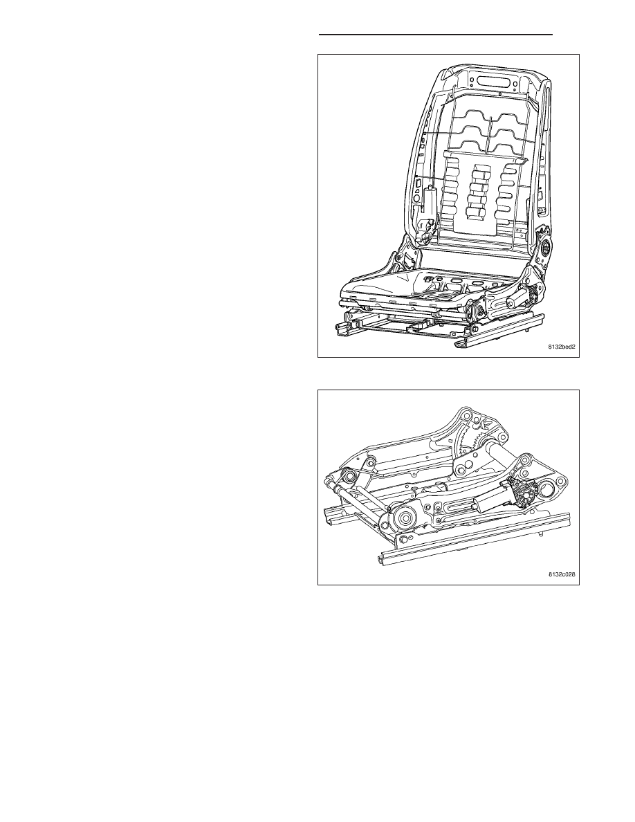
Power Seat Adjuster - The power seat adjuster
is made up of the upper and lower power seat
adjuster assemblies. The driver upper power seat
adjuster contains two reversible motors that are
connected to worm-drive gearboxes that move
the seat adjuster through a combination of
screw-type drive units. These motors are the
height adjust motor and the front tilt motor. On
vehicles equipped with non-memory power seats,
each

motor

contains

a

self-resetting

circuit

breaker to protect it from overload. On vehicles
equipped with memory power seats the motor
overload protection is a function of the Memory
Seat Module (MSM). Consecutive or frequent
resetting of the circuit breakers may damaged
the motors. There are no motors on the passenger upper power seat adjuster.
The height adjust motor is located on the rear of the upper power seat adjuster assembly and controls the up
and down movement of the entire seat. The height adjust motor can be serviced separately from the power
seat adjuster assembly.

8N - 288

POWER SEATS - SERVICE INFORMATION

WK

The front tilt motor is located on the front of the
upper power seat adjuster assembly and controls
the up and down movement of the seat front
only. The front tilt motor can be serviced sepa-
rately from the power seat adjuster assembly.

The driver and passenger lower power seat
adjusters contain one reversible motor that is
connected to a worm-drive gearbox that moves
the seat adjuster through a screw-type drive unit.
On vehicles equipped with non-memory power
seats, the motor will contain a self-resetting cir-
cuit breaker to protect it from overload. On vehi-
cles equipped with memory power seats the
motor overload protection is a function of the
Memory Seat Module (MSM). Consecutive or fre-
quent resetting of the circuit breakers may dam-
aged the motors. The motor is part of the lower
power seat track unit and must be replaced as
an assembly, (Refer to 23 - BODY/SEATS/SEAT
ADJUSTERS - REMOVAL).

Power Seat Recliner - The power seat recliner replaces the manual seat recliner.
The power seat option includes an electrically
operated power seat back recliner mechanism.
The power seat recliner switch is integral to the
power seat switch assembly, but is actuated with
a separate switch knob.
The power seat recliner motor assembly is
mounted in the place of a seat hinge on the out-
board side of the seat. The upper hinge plate of
the power seat recliner mechanism is secured
with two screws to the seat back frame and is
concealed beneath the seat back trim cover and
padding. The lower hinge plate and the motor
and drive unit of the power seat recliner mecha-
nism is secured with two screws to the seat
cushion frame, and is concealed by the outboard
seat cushion side shield.
The

power

seat

recliner

motor

cannot

be

repaired. If the unit is inoperative or damaged,
the seat back frame must be replaced, (Refer to
8

-

ELECTRICAL/POWER

SEATS/POWER

SEAT MOTOR - REMOVAL).

Power Seat Switches - Vehicles may be equipped with driver only, or driver and passenger power seat

WK

POWER SEATS - SERVICE INFORMATION

8N - 289

switches. One seat switch is used for each front
seat. The power seat switches are paddle-type
levers mounted on the outboard seat side
shields. Movement of the seat cushions and
backs mimics the action of the switch paddles.
(Refer to 8 - ELECTRICAL/POWER SEATS/
SEAT SWITCH - DESCRIPTION) for additional
information.

MEMORY SEAT SYSTEM

An electronic memory seat system is available on certain models. The memory system is able to store and recall all
driver side power seat positions, and the drivers side view mirror positions. The system can be set for two different
drivers. On vehicles with a factory installed radio connected to the Controller Area Network (CAN) data bus network,
the memory system is also able to store and recall up to twenty radio station presets (ten AM and ten FM), also for
two drivers. The memory system also will store and recall the last station listened to for each driver, even if it is not
one of the twenty preset stations.

The memory system will automatically recall all of these settings when a button of the memory switch is depressed,
or when the doors are unlocked using the Remote Keyless Entry (RKE) transmitter (if enabled). If the vehicle has
more than two drivers the RKE transmitter recall of memory features can be disabled. This is a customer program-
mable feature of the overhead console.

The memory system also has a easy exit feature that will move the driver seat rearward 55 millimeters or to the end
of its travel, whichever occurs first, when the key is removed from the ignition switch lock cylinder. This is a cus-
tomer programmable feature of the overhead console.

The memory system includes the following components:

Memory Selector Switch - located in the driver door trim panel.

Driver Memory Mirror Module (DMMM) - located in the driver door, behind the trim panel.

Passenger Memory Mirror Module (PMMM) - located in the passenger door, behind the trim panel.

Hall Effect Sensors - Drivers Mirror - The hall effect sensor is permanently installed on the drivers side view
mirror motor. This hall effect sensor is used to provide a reference signal to the memory heated seat mirror
module, letting the module know the exact position of the mirror.

Sentry Key Remote Entry Module (SKREEM) - located at ignition key cylinder.

Remote Keyless Entry (RKE) Transmitter - located with ignition key.

Memory Seat Module (MSM) - located underneath the driver seat and also controls the Adjustable Pedals.

Hall Effect Sensors - Seat Track - These hall effect sensors are permanently installed in each of the power
seat track motors. They are used to provide a reference signal to the memory heated seat mirror module,
letting the module know the exact position of the seat cushion and recliner.

Radio - located in the instrument panel center stack.

Automatic Temperature Control (ATC) - located in the instrument panel center stack.

Certain functions and features of the memory system rely upon resources shared with other electronic modules in
the vehicle over the Controller Area Network (CAN) bus. The CAN bus allows the sharing of sensor information.
This helps to reduce wire harness complexity, internal controller hardware, and component sensor current loads. At
the same time, this system provides increased reliability, enhanced diagnostics, and allows the addition of many
new feature capabilities. For diagnosis of these electronic modules or of the CAN bus, the use of a scan tool and
the proper diagnostic information are needed.

8N - 290

POWER SEATS - SERVICE INFORMATION

WK

OPERATION

POWER SEAT SYSTEM

The power seat system receives battery current through a 50 amp fuse in the Power Distribution Center (PDC) so
that the power seats remain operational, regardless of the ignition switch position.

When a power seat switch is actuated, a battery feed and a ground path are applied through the power seat switch
contacts to the appropriate motor or motors. The motor and drive unit operate to move the seat in the selected
direction until the switch is released, or until the travel limit of the power seat track is reached. When the switch is
moved in the opposite direction, the battery feed and ground path to the motor is reversed through the switch con-
tacts. This causes the motor to run in the opposite direction.

MEMORY SEAT SYSTEM

The Memory Seat Module (MSM) receives battery current through a 50 amp fuse in the Power Distribution Center
(PDC) so that the power seats remain operational, regardless of the ignition switch position. When the driver mem-
ory seat switch control knob is actuated, a resistance signal is sent to the MSM via the Controller Area Network
(CAN) bus circuit. The MSM is responsible for the 12v battery feed and ground path to the power seat adjuster
motor. The adjuster motor operates to move the power seat adjuster mechanism through its drive unit in the
selected direction until the switch is released, or until the travel limit of the adjuster is reached.

The MSM receives memory set/position switch input through the CAN bus circuit. The MSM also receives hard
wired input from the hall effect sensors, mounted on each of the driver power seat adjuster motors and the driver
side view mirror motor. The programmed software in the module allows it to know where the seat/mirror is located
in its designed travel by a pulse count generated from the hall effect sensors. This way, when the memory switch is
depressed the module will power the seat adjuster/mirror motors until the correct preset location is achieved. The
module will prevent the seat memory recall function from being initiated, if the transmission gear selector lever is not
in the Park position, or if the vehicle is moving. These inputs are monitored over the Controller Area Network (CAN)
bus circuit by the MSM.

A memory setting is saved by pressing the “set” button, then pressing either the memory “1” or “2” button within 5
seconds of pressing the “set” button.

A memory setting is recalled by pressing either the memory “1” or “2” button, or by pressing the unlock button on
a “linked” Remote Keyless Entry (RKE) transmitter.

For driver safety, memorized settings can not be recalled if the transmission is in a position other than Park or the
seat belt is latched.

DIAGNOSIS AND TESTING

MEMORY SEAT SYSTEM

In order to obtain conclusive testing of the power seats with and without the memory system option, the Controller
Area Network (CAN) bus, and all of the electronic modules that provide inputs to, or receive outputs from the mem-
ory system components must be checked. Use a scan tool and the proper diagnostic information to accurately diag-
nose the power seat/memory seat systems.

NOTE: Vehicles equipped with the memory/heated seat option utilize a low voltage cut-off feature. This fea-
ture turns off the 12v power to the power seat system anytime vehicle voltage is below 11.0v. Be certain to
check the vehicle electrical system for proper voltage anytime the power seat system appears inoperative.

Before any testing of the power seat system is attempted, the battery should be fully-charged.

POWER SEAT ADJUSTER

Operate the power seat switch and move the seat in all directions. The seat should move in each of the selected
directions.

If the power seat adjuster fails to operate in more than one direction, proceed as follows:

1. Inspect the power seat adjuster motors to ensure the electrical connectors are fully seated to the motors. If OK,

go to Step 2. If not OK, connect the electrical connector to the fully seated position.

WK

POWER SEATS - SERVICE INFORMATION

8N - 291


Content   ..  530  531  532  533   ..