Jeep Grand Cherokee WK. Manual - part 511
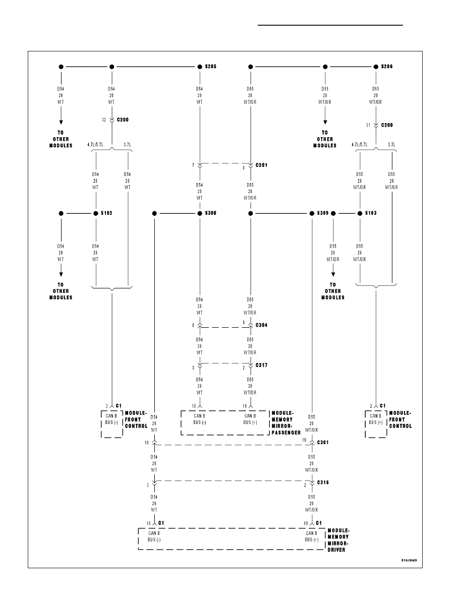
U1000–CAN B BUS (+) CIRCUIT– MEMORY MIRROR MODULE
8N - 204
POWER MIRRORS - ELECTRICAL DIAGNOSTICS
WK
|
|
|
U1000–CAN B BUS (+) CIRCUIT– MEMORY MIRROR MODULE 8N - 204 POWER MIRRORS - ELECTRICAL DIAGNOSTICS WK |