Jeep Grand Cherokee WK. Manual - part 497
B1D1F, B1D2B–MIRROR VERTICAL MOTOR CONTROL CIRCUIT LOW – MEMORY MIRROR MODULE (CONTINUED)
5.
CHECK THE (P71) DRIVER MIRROR VERTICAL DRIVER CIRCUIT FOR A SHORT TO THE (P69) DRIVER
MIRROR SENSOR GROUND CIRCUIT OR THE (P72) PASSENGER MIRROR VERTICAL DRIVER CIRCUIT
FOR A SHORT TO THE (P66) PASSENGER MIRROR SENSOR GROUND CIRCUIT
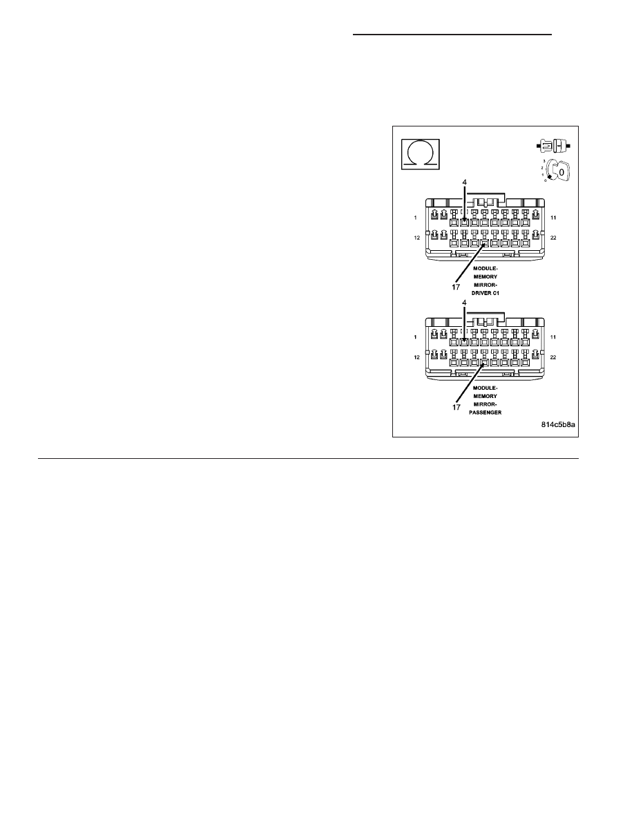
For the Driver Memory Mirror System, proceed as follows:
•
Measure the resistance between the (P71) Driver Mirror Vertical
Driver circuit and the (P69) Driver Mirror Sensor Ground circuit in
the Driver Memory Mirror Module C1 connector.
For the Passenger Memory Mirror System, proceed as follows:
•
Measure the resistance between the (P72) Passenger Mirror Ver-
tical Driver circuit and the (P66) Passenger Mirror Sensor Ground
circuit in the Passenger Memory Mirror Module connector.
Is the resistance below 10000.0 ohms?
Yes, Driver MMM
Repair the (P71) Driver Mirror Vertical Driver circuit for a
short to the (P69) Driver Mirror Sensor Ground circuit.
Perform BODY VERIFICATION TEST – VER 1. (Refer to 8
- ELECTRICAL/ELECTRONIC CONTROL MODULES -
STANDARD PROCEDURE).
Yes, Passenger MMM
Repair the (P72) Passenger Mirror Vertical Driver circuit
for a short to the (P66) Passenger Mirror Sensor Ground
circuit.
Perform BODY VERIFICATION TEST – VER 1. (Refer to 8
- ELECTRICAL/ELECTRONIC CONTROL MODULES -
STANDARD PROCEDURE).
No
>> Go To 6
8N - 148
POWER MIRRORS - ELECTRICAL DIAGNOSTICS
WK