Jeep Grand Cherokee WK. Manual - part 490
B1D04–MIRROR ADJUST SWITCH INPUT CIRCUIT/PERFORMANCE – DRIVER MEMORY MIRROR
MODULE (CONTINUED)
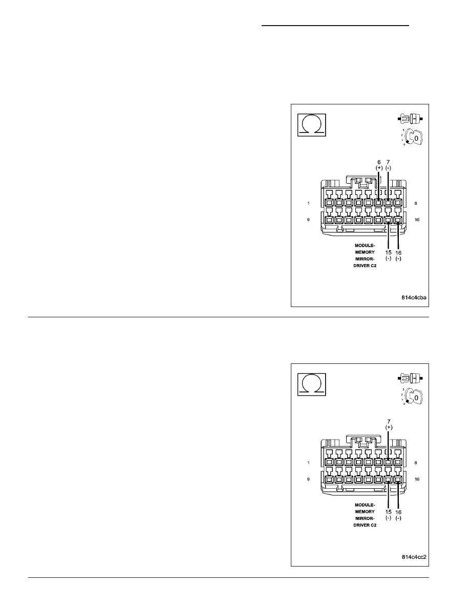
10.
CHECK THE (P76) MIRROR COMMON DRIVER CIRCUIT FOR A SHORT TO THE (P705) MIRROR
VERTICAL DOWN SWITCH SENSE CIRCUIT, THE (P704) MIRROR HORIZONTAL RIGHT SWITCH
SENSE CIRCUIT, & THE (P706) MIRROR VERTICAL UP SWITCH SENSE CIRCUIT
Measure the resistance between the (P76) Mirror Common Driver cir-
cuit and the (P705) Mirror Vertical Down Switch Sense circuit, the
(P704) Mirror Horizontal Right Switch Sense circuit, and the (P706)
Mirror Vertical Up Switch Sense circuit in the Driver Memory Mirror
Module C2 connector.
Is the resistance below 10000.0 ohms on any of the circuits?
Yes
>> Repair all circuits with a resistance below 10000.0 ohms
for a short to the (P76) Mirror Common Driver circuit.
Perform BODY VERIFICATION TEST – VER 1. (Refer to 8
- ELECTRICAL/ELECTRONIC CONTROL MODULES -
STANDARD PROCEDURE).
No
>> Go To 11
11.
CHECK THE (P705) MIRROR VERTICAL DOWN SWITCH SENSE CIRCUIT FOR A SHORT TO THE
(P704) MIRROR HORIZONTAL RIGHT SWITCH SENSE CIRCUIT, & THE (P706) MIRROR VERTICAL UP
SWITCH SENSE CIRCUIT
Measure the resistance between the (P705) Mirror Vertical Down
Switch Sense circuit and the (P704) Mirror Horizontal Right Switch
Sense circuit, and the (P706) Mirror Vertical Up Switch Sense circuit in
the Driver Memory Mirror Module C2 connector.
Is the resistance below 10000.0 ohms on any of the circuits?
Yes
>> Repair all circuits with a resistance below 10000.0 ohms
for a short to the (P705) Mirror Vertical Down Switch
Sense circuit.
Perform BODY VERIFICATION TEST – VER 1. (Refer to 8
- ELECTRICAL/ELECTRONIC CONTROL MODULES -
STANDARD PROCEDURE).
No
>> Go To 12
8N - 120
POWER MIRRORS - ELECTRICAL DIAGNOSTICS
WK