Jeep Grand Cherokee WK. Manual - part 476
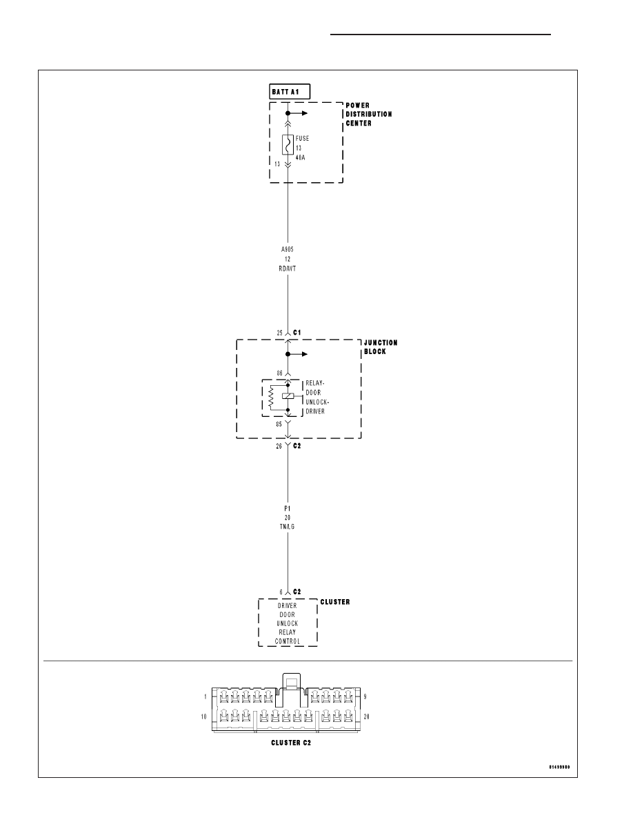
B1836–DRIVER DOOR UNLOCK CONTROL CIRCUIT HIGH– CLUSTER
8N - 64
POWER LOCKS - ELECTRICAL DIAGNOSTICS
WK
|
|
|
B1836–DRIVER DOOR UNLOCK CONTROL CIRCUIT HIGH– CLUSTER 8N - 64 POWER LOCKS - ELECTRICAL DIAGNOSTICS WK |