Jeep Grand Cherokee WK. Manual - part 401
Each coil fires 2 spark plugs simultaneously on each of the cylinder banks (one cylinder on compression stroke and
one cylinder on exhaust stroke). EXAMPLE : When the #1 cylinder is on compression stroke and ready for spark,
the #1 coil will fire one of the dual spark plugs on the #1 cylinder (directly below the coil). The other dual spark plug
on the #1 cylinder will be fired by the #6 coil. At the same time, the #1 coil will fire a “wasted spark” to one of the
dual spark plugs at the #6 cylinder as coil #6 also fires a “wasted spark” to one of the dual spark plugs at the #6
cylinder.
The firing order is paired at cylinders 1/6, 2/3, 4/7, 5/8. Basic cylinder firing order is 1–8–4–3–6–5–7–2.
Battery voltage is supplied to all of the ignition coils positive terminals from the ASD relay. If the PCM does not see
a signal from the crankshaft and camshaft sensors (indicating the ignition key is ON but the engine is not running),
it will shut down the ASD circuit.
Base ignition timing is not adjustable on the 5.7L V-8 engine. By controlling the coil ground circuits, the PCM is
able to set the base timing and adjust the ignition timing advance. This is done to meet changing engine operating
conditions.
The PCM adjusts ignition timing based on inputs it receives from:
•
The engine coolant temperature sensor
•
The crankshaft position sensor (engine speed)
•
The camshaft position sensor (crankshaft position)
•
The manifold absolute pressure (MAP) sensor
•
The throttle position sensor
•
Transmission gear selection
REMOVAL
3.7L V-6
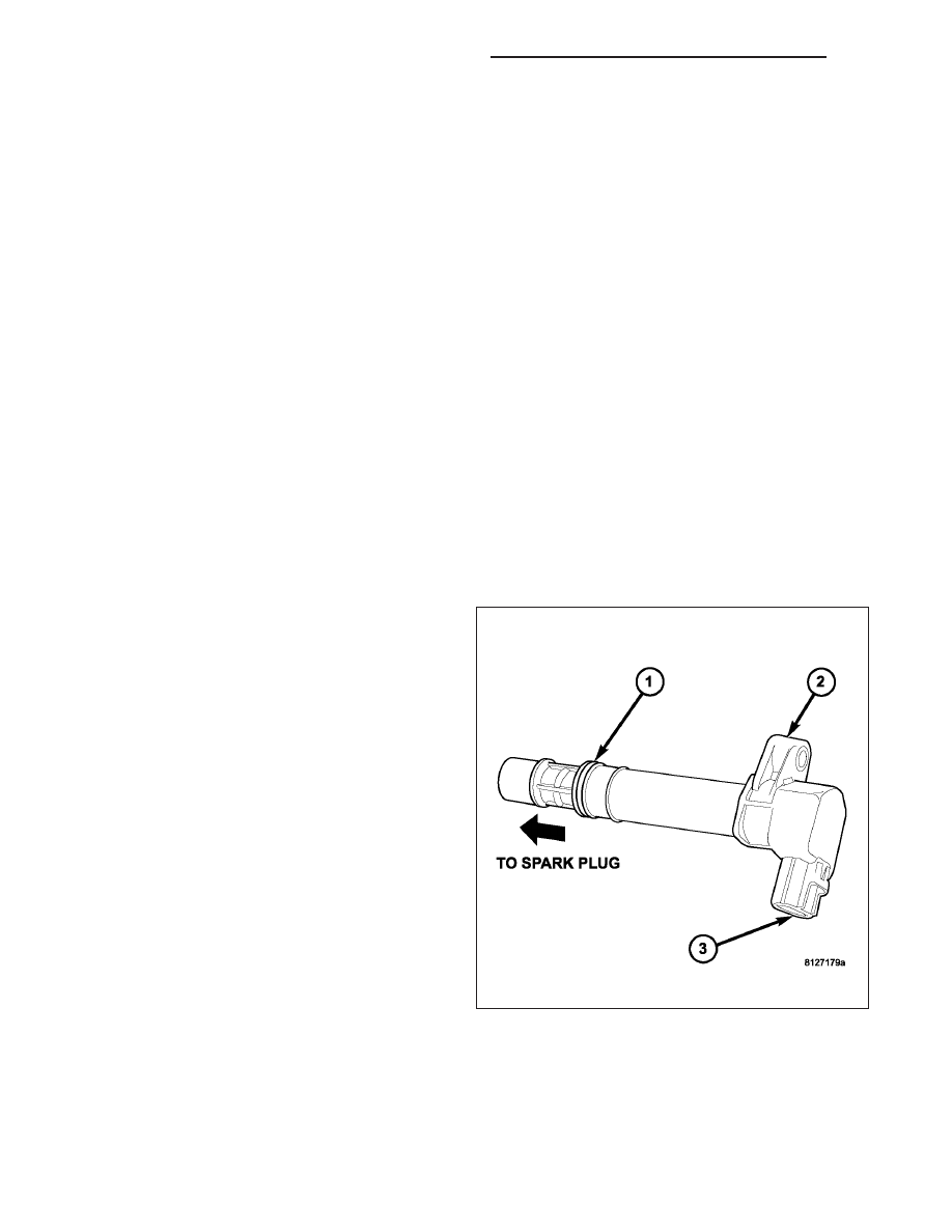
An individual ignition coil is used for each spark plug
(2). The coil fits into machined holes in the cylinder
head. A mounting stud/nut secures each coil to the top
of the intake manifold. The bottom of the coil is
equipped with a rubber boot to seal the spark plug to
the coil. Inside each rubber boot is a spring. The
spring is used for a mechanical contact between the
coil and the top of the spark plug. These rubber boots
and springs are a permanent part of the coil and are
not serviced separately. An o-ring (1) is used to seal
the coil at the opening into the cylinder head.
1. Depending on which coil is being removed, the
throttle body air intake tube or intake box may
need to be removed to gain access to coil.
2. Disconnect electrical connector from coil by push-
ing downward on release lock on top of connector
and pull connector from coil.
3. Clean area at base of coil with compressed air
before removal.
8I - 24
IGNITION SYSTEM - SERVICE INFORMATION
WK