Jeep Grand Cherokee WK. Manual - part 392


  Index      Jeep     Jeep Grand Cherokee WK - service repair manual 2005 year


Search            


Content   ..  390  391  392  393   ..


Jeep Grand Cherokee WK. Manual - part 392


B2336–HORN CONTROL CIRCUIT LOW – FCM (CONTINUED)

10.

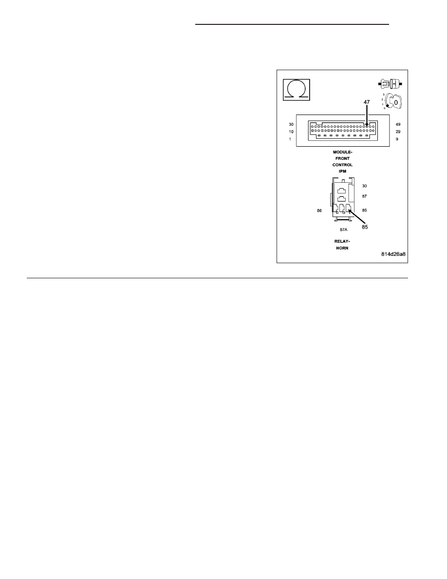
CHECK THE (X4) HORN RELAY CONTROL CIRCUIT FOR AN OPEN

Remove the Front Control Module (FCM) in accordance with the Ser-
vice Information.

Measure the resistance of the (X4) Horn Relay Control circuit between
Cavity 85 of the Horn Relay connector in the Integrated Power Module
(IPM) and Cavity 47 of the FCM 49-Way connector.

Is the resistance below 5.0 ohms?

Yes

>> Replace the Front Control Module (FCM) in accordance

with the Service Information.

Perform BODY VERIFICATION TEST - VER 1. (Refer to 8
- ELECTRICAL/ELECTRONIC CONTROL MODULES -
STANDARD PROCEDURE).

No

>> Replace the Integrated Power Module (IPM) in accordance

with the Service Information.

Perform BODY VERIFICATION TEST - VER 1. (Refer to 8
- ELECTRICAL/ELECTRONIC CONTROL MODULES -
STANDARD PROCEDURE).

8H - 8

HORN - ELECTRICAL DIAGNOSTICS

WK

B2337–HORN CONTROL CIRCUIT HIGH – FCM

WK

HORN - ELECTRICAL DIAGNOSTICS

8H - 9

B2337–HORN CONTROL CIRCUIT HIGH – FCM (CONTINUED)

For the Horn System circuit diagram (Refer to 8 - ELECTRICAL/HORN - SCHEMATICS AND DIAGRAMS).

For a complete wiring diagram Refer to Section 8W.

When Monitored:
Continuously

Set Condition:
If the Front Control Module (FCM) senses excessive voltage on the (X4) Horn Relay Control circuit.

Possible Causes

(X4) HORN RELAY CONTROL CIRCUIT SHORTED TO VOLTAGE

HORN RELAY

INTEGRATED POWER MODULE (IPM)

FRONT CONTROL MODULE (FCM)

Diagnostic Test

1.

TEST FOR INTERMITTENT CONDITION

Turn the ignition on.

With the scan tool, record and erase DTCs.

Operate the Horn Switch several times.

Cycle the ignition from on to off 3 times and leave on.

With the scan tool, read DTCs.

Does the scan tool display: B2337 HORN CONTROL CIRCUIT HIGH?

Yes

>> Go To 2

No

>> The conditions that caused this code to set are not present at this time. Using the wiring diagram/sche-

matic as a guide, inspect the wiring and connectors.

Perform BODY VERIFICATION TEST - VER 1. (Refer to 8 - ELECTRICAL/ELECTRONIC CONTROL
MODULES - STANDARD PROCEDURE).

2.

CHECK FOR A SHORTED HORN RELAY

Turn the ignition off.

Install a known good relay in place of the Horn Relay.

Turn the ignition on.

With the scan tool erase DTCs.

Operate the Horn Switch several times.

Cycle the ignition from on to off 3 times and leave on.

With the scan tool, read DTCs.

Does the scan tool display: B2337 HORN CONTROL CIRCUIT
HIGH?

Yes

>> Go To 3

No

>> Replace the original Horn Relay.

Perform BODY VERIFICATION TEST - VER 1. (Refer to 8
- ELECTRICAL/ELECTRONIC CONTROL MODULES -
STANDARD PROCEDURE).

8H - 10

HORN - ELECTRICAL DIAGNOSTICS

WK

B2337–HORN CONTROL CIRCUIT HIGH – FCM (CONTINUED)

3.

CHECK THE (X4) HORN RELAY CONTROL CIRCUIT FOR A SHORT TO VOLTAGE

Turn the ignition off.

Remove the Horn Relay.

Remove the Front Control Module (FCM) in accordance with the Ser-
vice Information.

Turn the ignition on.

Measure the voltage of the (X4) Horn Relay Control circuit.

Is the voltage above 0.2 volts?

Yes

>> Replace the Integrated Power Module (IPM) in accordance

with the Service Information.

Perform BODY VERIFICATION TEST - VER 1. (Refer to 8
- ELECTRICAL/ELECTRONIC CONTROL MODULES -
STANDARD PROCEDURE).

No

>> Replace the Front Control Module (FCM) in accordance

with the Service Information.

Perform BODY VERIFICATION TEST - VER 1. (Refer to 8
- ELECTRICAL/ELECTRONIC CONTROL MODULES - STANDARD PROCEDURE).

WK

HORN - ELECTRICAL DIAGNOSTICS

8H - 11


Content   ..  390  391  392  393   ..