Jeep Grand Cherokee WK. Manual - part 367


  Index      Jeep     Jeep Grand Cherokee WK - service repair manual 2005 year


Search            


Content   ..  365  366  367  368   ..


Jeep Grand Cherokee WK. Manual - part 367


To prevent a gasoline engine from starting, remove the Automatic ShutDown (ASD) relay. The ASD relay is
located in the Integrated Power Module (IPM), in the engine compartment. See the fuse and relay layout label
on the underside of the IPM cover for ASD relay identification and location.

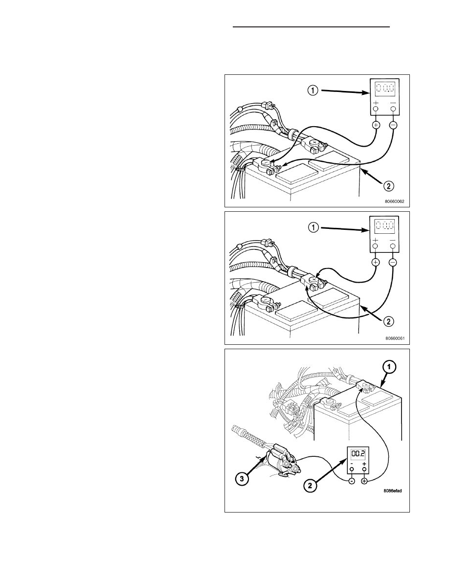
1. Connect the positive lead of the voltmeter (1) to the

battery negative terminal post. Connect the nega-
tive lead of the voltmeter (1) to the battery negative
cable terminal clamp. Rotate and hold the ignition
switch in the Start position. Observe the voltmeter.
If voltage is detected, correct the poor connection
between the battery negative cable terminal clamp
and the battery negative terminal post.

2. Connect the positive lead of the voltmeter (1) to the

battery positive terminal post. Connect the negative
lead of the voltmeter to the battery positive cable
terminal clamp. Rotate and hold the ignition switch
in the Start position. Observe the voltmeter. If volt-
age is detected, correct the poor connection
between the battery positive cable terminal clamp
and the battery positive terminal post.

3. Connect the voltmeter (2) to measure between the

battery positive cable terminal clamp (1) and the
starter solenoid (3) B(+) terminal stud. Rotate and
hold the ignition switch in the Start position.
Observe the voltmeter. If the reading is above 0.2
volt, clean and tighten the battery positive cable
eyelet terminal connection at the starter solenoid
B(+) terminal stud. Repeat the test. If the reading is
still above 0.2 volt, replace the faulty battery posi-
tive cable.

8F - 20

BATTERY SYSTEM - SERVICE INFORMATION

WK

4. Connect the voltmeter (1) to measure between the

battery (2) negative cable terminal clamp and a
good clean ground (3) on the engine block. Rotate
and hold the ignition switch in the Start position.
Observe the voltmeter. If the reading is above 0.2
volt, clean and tighten the battery negative cable
eyelet terminal connection to the engine block.
Repeat the test. If the reading is still above 0.2
volt, replace the faulty battery negative cable.

REMOVAL

NOTE: It may be necessary to use a battery termi-
nal puller (2) if the battery cable terminal clamps
are seized on to the battery posts.

Both the battery negative cable (2) and the battery
positive cable (4) are serviced in the battery wire har-
ness (10). If either battery cable is damaged or faulty,
the battery wire harness assembly must be replaced.

1. Turn the ignition switch to the Off position. Be cer-

tain that all electrical accessories are turned off.

2. Disconnect the battery negative cable terminal

clamp (2) from the battery negative terminal post. If
necessary, use a battery terminal puller to remove
the terminal clamp from the battery post.

3. Lift the battery positive cable terminal clamp cover

(3) to gain access to the pinch-bolt hex nut.

WK

BATTERY SYSTEM - SERVICE INFORMATION

8F - 21

4. Disconnect the battery positive cable terminal clamp (4) from the battery positive terminal post. If necessary, use

a battery terminal puller to remove the terminal clamp from the battery post.

5. Remove the screw (1) that secures the battery

negative cable eyelet terminal (2) to the inner
fender (3).

6. Unlatch and open the cover on the Power Distribu-

tion Center (PDC)(1) and Integrated Power Module
(IPM)(2).

8F - 22

BATTERY SYSTEM - SERVICE INFORMATION

WK

7. Remove the two nuts that secure the battery posi-

tive cable eyelet terminal to the B(+) terminal studs
in the PDC.

8. Remove the nut that secures the battery positive

cable eyelet terminal to the B(+) terminal stud in
the IPM.

9. Remove both battery positive cable eyelet termi-

nals from the B(+) terminal studs in the PDC and
IPM.

10. Disconnect the battery wire harness three pin

connector (11).

11. Remove the battery wire harness three pin con-

nector (11) from the battery tray (12).

12. On 3.7L and 4.7L engines remove the nut (6) that

secures the generator output cable eyelet terminal
(7) to the generator output terminal stud.

13. Remove the generator output cable eyelet termi-

nal from the generator output terminal stud.

14. Disconnect the battery wire harness connector (8)

from the generator field terminal connector recep-
tacle on the back of the generator.

15. Remove the battery wire harness retaining clip (9)

from the valve cover stud.

WK

BATTERY SYSTEM - SERVICE INFORMATION

8F - 23


Content   ..  365  366  367  368   ..