Jeep Grand Cherokee WK. Manual - part 279
B212A-PTS DISPLAY SUPPLY VOLTAGE LOW (CONTINUED)
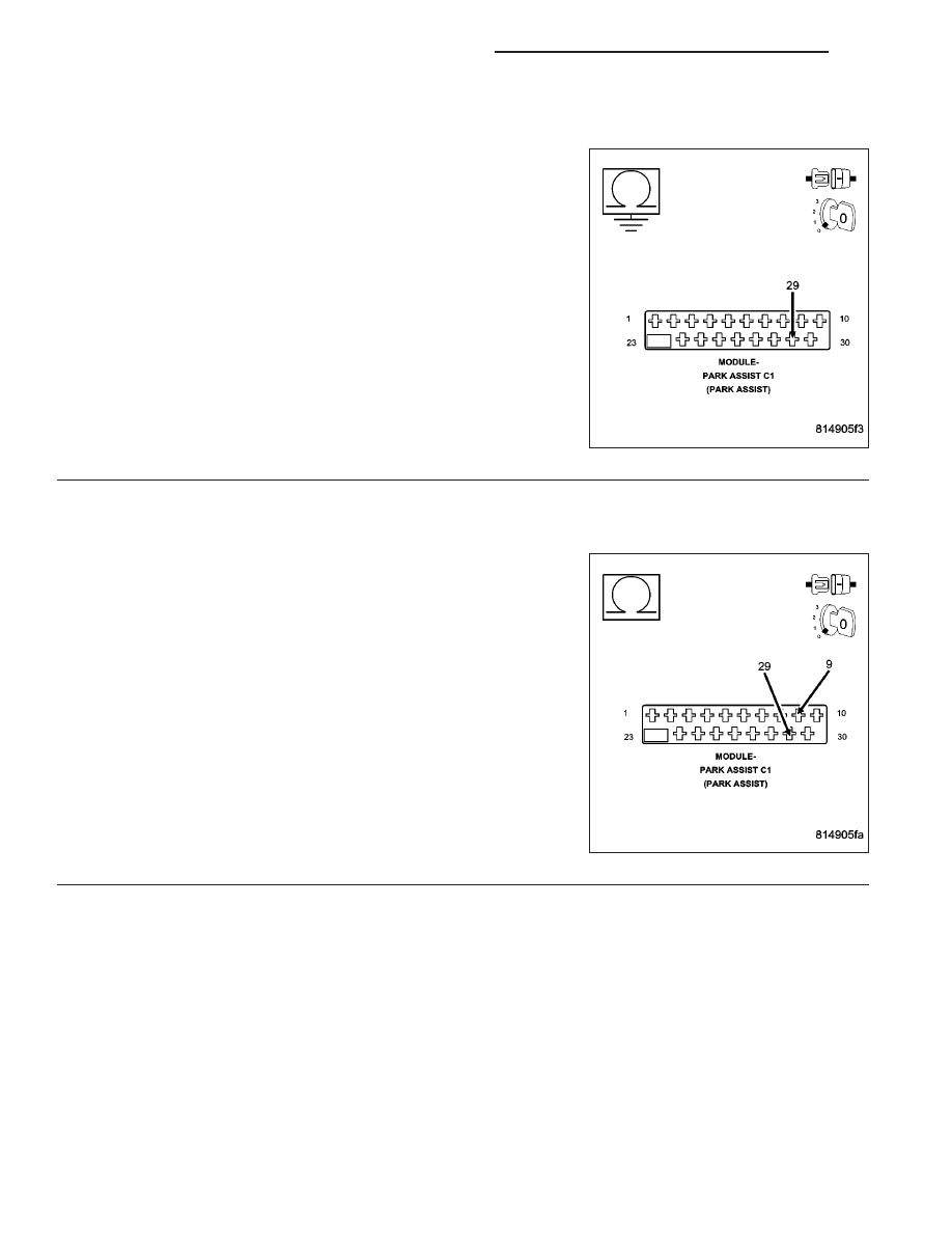
2.
CHECK PARK ASSIST MODULE FOR AN INTERNAL SHORT TO GROUND
Turn the ignition off.
Disconnect the Park Assist Module harness connector.
Measure the resistance between ground and the (X777) Park Assist
Display Supply circuit.
Is the resistance below 10K ohms?
Yes
>> Go To 3
No
>> Replace the Park Assist Module in accordance with the
service information.
Perform BODY VERIFICATION TEST - VER 1. (Refer to 8
- ELECTRICAL/ELECTRONIC CONTROL MODULES -
STANDARD PROCEDURE)
3.
CHECK THE (X777) PARK ASSIST DISPLAY SUPPLY CIRCUIT FOR A SHORT TO THE (Z171) PARK
ASSIST DISPLAY GROUND CIRCUIT
Disconnect the Park Assist Display harness connector.
Measure the resistance between the (X777) Park Assist Display Sup-
ply circuit and the (Z171) Park Assist Display Ground circuit.
Is the resistance below 10K ohms?
Yes
>> Repair the (X777) Park Assist Display Supply circuit for a
short to the (Z171) Park Assist Display Ground circuit.
Perform BODY VERIFICATION TEST - VER 1. (Refer to 8
- ELECTRICAL/ELECTRONIC CONTROL MODULES -
STANDARD PROCEDURE)
No
>> Go To 4
8B - 42
CHIME/BUZZER - ELECTRICAL DIAGNOSTICS
WK