Jeep Grand Cherokee WK. Manual - part 186
U0002-CAN C BUS OFF PERFORMANCE (CONTINUED)
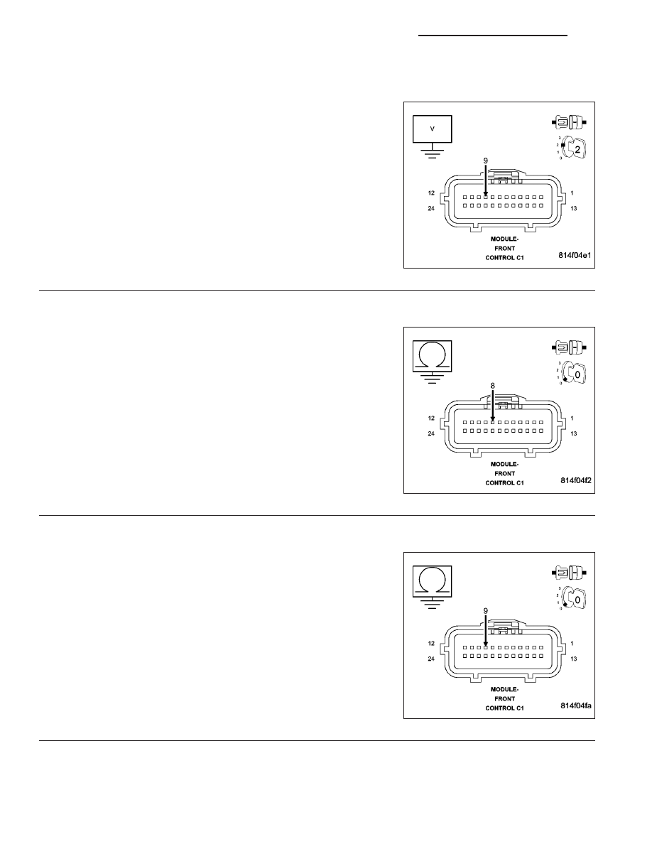
8.
(D64) CAN C BUS (-) CIRCUIT SHORTED TO VOLTAGE
Measure the voltage between the (D64) CAN C Bus (-) circuit and
ground.
Is there any voltage present?
Yes
>> Repair the (D64) CAN C Bus (-) circuit for a short to volt-
age.
Perform BODY VERIFICATION TEST - VER 1.
No
>> Go To 9
9.
(D65) CAN C BUS (+) CIRCUIT SHORTED TO GROUND
Turn the ignition off.
Measure the resistance between ground and the (D65) CAN C Bus (+)
circuit.
Is any resistance present?
Yes
>> Repair the (D65) CAN C Bus (+) circuit for a short to
ground.
Perform BODY VERIFICATION TEST - VER 1.
No
>> Go To 10
10.
(D64) CAN C BUS (-) CIRCUIT SHORTED TO GROUND
Measure the resistance between ground and the (D64) CAN C Bus (-)
circuit.
Is any resistance present?
Yes
>> Repair the (D64) CAN C Bus (-) circuit for a short to
ground.
Perform BODY VERIFICATION TEST - VER 1.
No
>> Go To 11
5 - 370
BRAKES - BRAKE CONTROLLER ELECTRICAL DIAGNOSTICS
WK