Content .. 1752 1753 1754 1755 ..
Jeep Grand Cherokee WK. Manual - part 1754
•
Panel Outlets - There are four panel outlets in the instrument panel, one located near each outboard end of
the instrument panel facing the rear of the vehicle and one located on each side of the instrument panel center
bezel.
•
Floor Outlets - There is one floor outlet located above each side of the floor panel center tunnel near the
dash panel. There is also one outlet located under each front seat.
•
Console Outlets - There are two console outlets located at the back of the center floor console facing the rear
of the vehicle.
OPERATION
Both the manual temperature control (MTC) and the automatic temperature control (ATC ) heating-A/C system are
blend-air type systems. In a blend-air system, a blend-air door controls the amount of conditioned air that is allowed
to flow through, or around, the heater core. In the available dual zone system, two blend-air doors are used to
provide completely independent side-to-side temperature control of the discharge air. The temperature control(s)
determines the discharge air temperature(s) by operating the blend door actuator(s), which move the blend-air
door(s). This design allows almost immediate control of output air temperature(s).
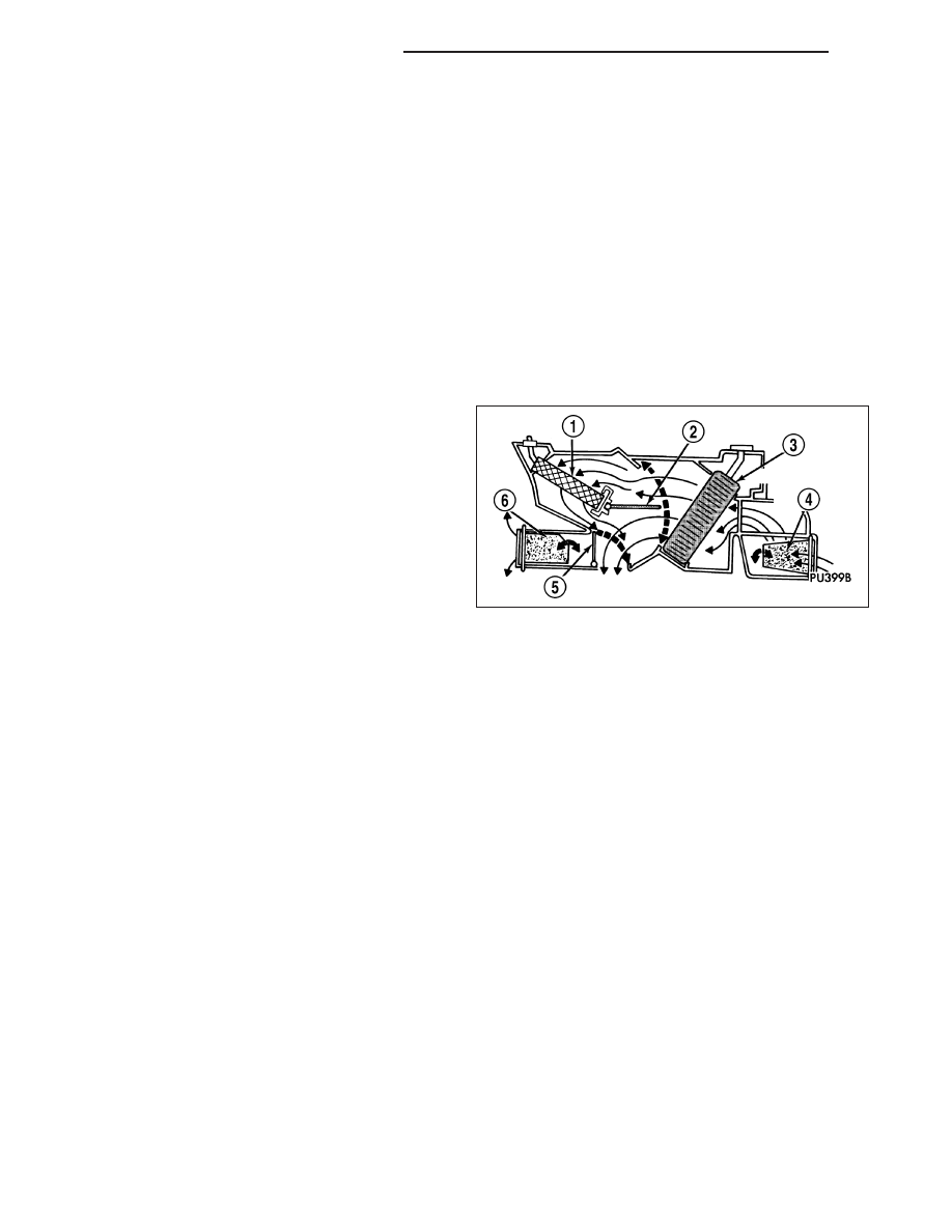
The heating-A/C system pulls outside (ambient) air
through the cowl opening at the base of the wind-
shield, then into the air inlet housing and through the
A/C evaporator (3). Air flow can be directed either
through or around the heater core (1). This is done by
adjusting the blend-air door(s) (2) with the temperature
control(s) located on the A/C-heater control in the
instrument panel. The air flow can then be directed
from the panel, floor and defrost outlets in various
combinations using the mode control located on the
A/C-heater control. Air flow velocity can be adjusted
with the blower speed control located on the A/C-
heater control.
The outside (fresh) air intake can be shut off by selecting the Recirculation Mode with the mode control. This will
operate an electrically actuated recirculation-air door (4) that closes off the fresh air intake and recirculates the air
that is already inside the vehicle.
The A/C compressor can be engaged in any mode by pressing the snowflake, A/C on/off button. It can also be
engaged by placing the mode control in the mix to defrost positions. This will remove heat and humidity from the air
before it is directed through or around the heater core. The mode control on the A/C-heater control is used to also
direct the conditioned air to the selected system outlets. The mode control uses an electric actuator to control the
mode-air doors (5 and 6).
The two slot-type defroster outlets receive airflow from the HVAC housing through the molded plastic defroster
ducts, which connect to the HVAC housing defroster outlets. The airflow from the defroster outlets is directed by
fixed vanes in the defroster outlet grilles and cannot be adjusted. The defroster outlet grilles are serviceable from
the instrument panel top cover.
The side window demister outlets receive airflow from the HVAC housing through the molded plastic demister ducts.
The demisters direct air from the HVAC housing through the outlets located on the top corners of the instrument
panel. The airflow from the side window demister outlets is directed by fixed vanes in the demister outlet grilles and
cannot be adjusted. The side window demister outlet grilles are not serviceable from the instrument panel. The
demisters operate when the controls are set in Heat, Bi-level, Mix and Defrost modes.
The four instrument panel outlets receive airflow from the HVAC housing through two molded plastic main panel
ducts. One duct directs air flow out of the right side instrument panel outlets, while the other duct delivers air flow
to the left side outlets. Each of these outlets can be individually adjusted to direct the flow of air.
The floor outlets receive airflow from the HVAC housing through the floor distribution ducts which are connected to
the rear of the HVAC air distribution housing. Two plastic rear distribution ducts and one center console duct attach
to the rear of the air distribution housing and provide conditioned air to the rear seating positions. The two console
outlets can be individually adjusted to direct the flow of air, but the floor outlets cannot be adjusted.
24 - 364
HVAC - SERVICE INFORMATION
WK