Content .. 1714 1715 1716 1717 ..
Jeep Grand Cherokee WK. Manual - part 1716
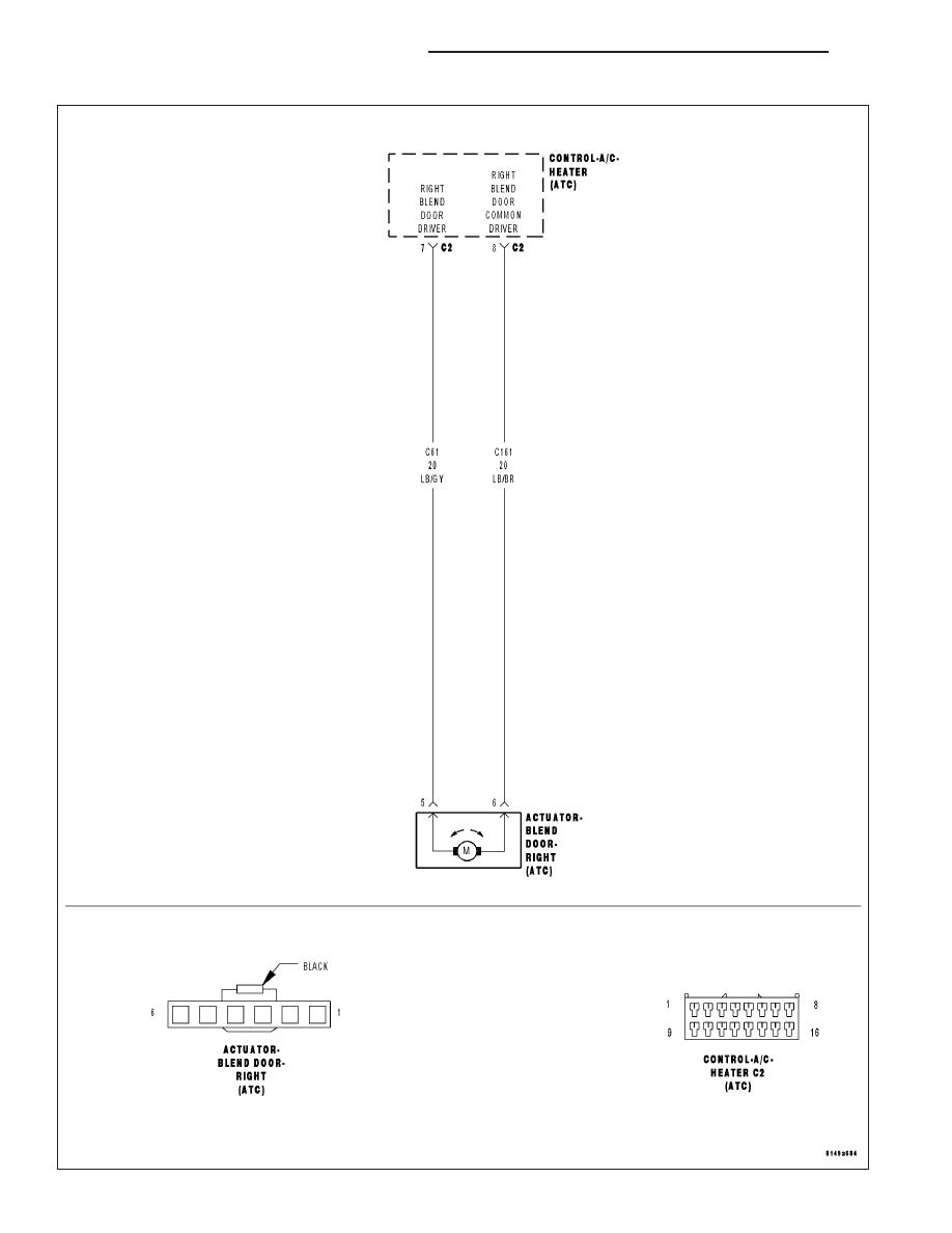
B10AC–RIGHT BLEND DOOR CONTROL CIRCUIT OPEN (ATC)
24 - 212
HVAC - ELECTRICAL DIAGNOSTICS
WK
|
|
|
Content .. 1714 1715 1716 1717 ..
B10AC–RIGHT BLEND DOOR CONTROL CIRCUIT OPEN (ATC) 24 - 212 HVAC - ELECTRICAL DIAGNOSTICS WK |