Content .. 1567 1568 1569 1570 ..
Jeep Grand Cherokee WK. Manual - part 1569
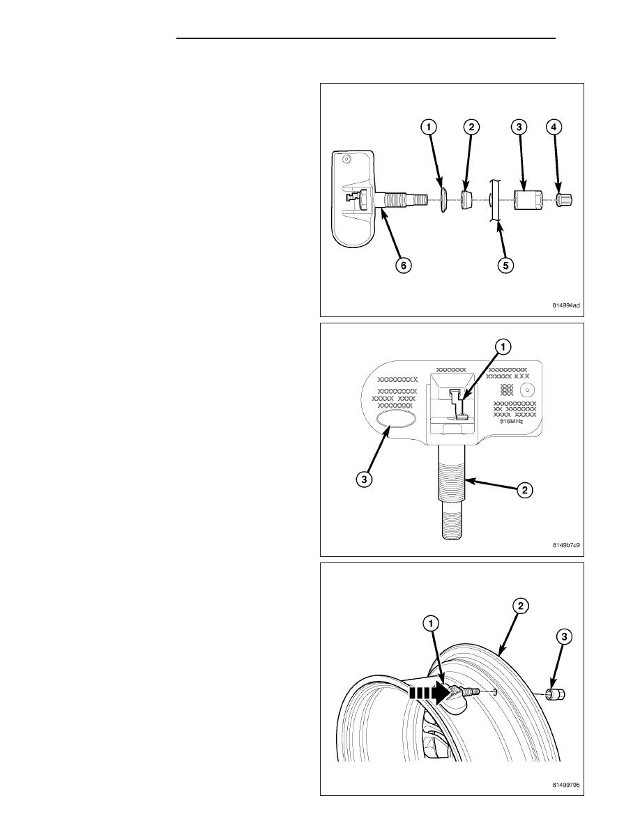
INSTALLATION
NOTE: Before reinstalling an existing tire pressure
sensor, replace seal (2) and metal washer (1) at
base of sensor valve stem (6) to ensure proper
sealing.
1. Wipe area clean around sensor/valve stem mount-
ing hole in wheel (5). Make sure surface of wheel
is not damaged.
CAUTION: To avoid damaging sensor antenna
strap (1), hold pressure against rear of metal valve
stem (2) while sensor is inserted through wheel
mounting hole and nut is installed.
2. Insert sensor (1) through wheel (2) as shown keep-
ing pressure against rear of metal valve stem (See
Arrow). Potted side of sensor is to be positioned
toward wheel. Do not attempt to mount sensor oth-
erwise, damage may occur.
3. Install sensor nut (with pressed-in washer) (3) by
hand.
22 - 24
TIRES/WHEELS
WK