Content .. 1504 1505 1506 1507 ..
Jeep Grand Cherokee WK. Manual - part 1506
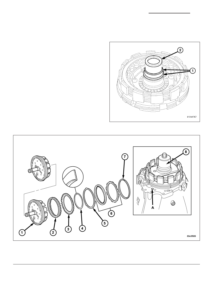
B1-HOLDING CLUTCH
DISASSEMBLY
1. Remove the teflon rings (1) from the B1 plate car-
rier hub (2).
Holding Clutch B1
1 - HOLDING CLUTCH B1 OUTER CARRIER
5 - DISC SPRING
2 - PISTON
6 - MULTIPLE DISC PACK
3 - DISC SPRING
7 - SNAP-RING
4 - SNAP-RING
8 - MULTI-USE SPRING COMPRESSOR 8900
21 - 834
AUTOMATIC TRANSMISSION - NAG1 - SERVICE INFORMATION
WK