Jeep Grand Cherokee WK. Manual - part 148


  Index      Jeep     Jeep Grand Cherokee WK - service repair manual 2005 year


Search            


Content   ..  146  147  148  149   ..


Jeep Grand Cherokee WK. Manual - part 148


C1046-LEFT FRONT WHEEL PRESSURE PHASE MONITORING (CONTINUED)

5.

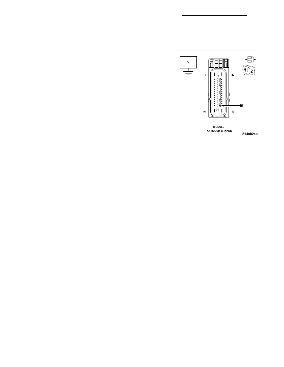
CHECK THE (B8) LEFT FRONT WSS SIGNAL VOLTAGE AT THE ANTI-LOCK BRAKE MODULE HARNESS
CONNECTOR

Turn the ignition off.

Turn the ignition on.

While back probing, measure the voltage between the (B8) Left Front
WSS Signal circuit at the Anti-Lock Brake Module harness connector
and chassis ground.

Slowly rotate the wheel by hand.

Did the (B8) Left Front WSS Signal circuit voltage toggle
between approximately 1.6 to .8 volts?

Yes

>> Replace the Anti-Lock Brake Module in accordance with

the Service Information.

Perform ABS VERIFICATION TEST - VER 1.

No

>> Repair the (B8) Left Front WSS Signal circuit for an open.

Perform ABS VERIFICATION TEST - VER 1.

5 - 218

BRAKES - BRAKE CONTROLLER ELECTRICAL DIAGNOSTICS

WK

C1047-RIGHT FRONT WHEEL PRESSURE PHASE MONITORING

WK

BRAKES - BRAKE CONTROLLER ELECTRICAL DIAGNOSTICS

5 - 219

C1047-RIGHT FRONT WHEEL PRESSURE PHASE MONITORING (CONTINUED)

For the Anti-Lock Brake System circuit diagram. (Refer to 5 - BRAKES - SCHEMATICS AND DIAGRAMS)

For a complete wiring diagram Refer to Section 8W.

When Monitored:
With the ignition on.

Set Condition:
When the Anti-Lock Brake Module detects a pressure reduction phase and the following pressure hold phase
is too long.

Possible Causes

TERMINAL/CONNECTOR/WIRING HARNESS/TONE WHEEL DAMAGE

(B6) RIGHT FRONT WSS SIGNAL CIRCUIT OPEN

RIGHT FRONT WHEEL SPEED SENSOR

ANTI-LOCK BRAKE MODULE

Diagnostic Test

1.

CHECK FOR A DTC C1047-RIGHT FRONT WHEEL PRESSURE PHASE MONITORING

NOTE: This DTC must be active for the results of this test to be valid.
Turn the ignition on.

With the scan tool, read DTCs.

Record DTC and Freeze Frame information.

With the scan tool, erase DTCs.

Cycle the ignition switch off then on.

CAUTION: Ensure brake capability is available before road testing.
Have an assistant test drive the vehicle in a straight line to 40 Km/h (25 mph) while monitoring all the WSS speeds
with the scan tool.

Did the RF WSS speed differ by 8 Km/h (5 mph) or show NO speed?

Yes

>> Go To 2

No

>> Refer to the INTERMITTENT CONDITION diagnostic procedure.

Perform ABS VERIFICATION TEST - VER 1.

2.

CHECK THE TERMINALS/CONNECTORS/WIRING HARNESS/TONE WHEEL FOR DAMAGE

NOTE: Check all related wiring for bruised, chafed, pierced, or partially broken wires.

NOTE: Check all related connectors for broken, bent, pushed out, or corroded terminals.

NOTE: Check the tone wheel teeth for missing teeth, cracks, or looseness. Teeth should be perfectly
square, not bent, or nicked.
Turn the ignition off.

Visually inspect the Anti-Lock Brake Module harness connector, Right Front WSS, Right Front WSS harness con-
nector, and Right Front WSS tone wheel (if applicable) for damage.

Were any problems found?

Yes

>> Repair as necessary.

Perform ABS VERIFICATION TEST - VER 1.

No

>> Go To 3

5 - 220

BRAKES - BRAKE CONTROLLER ELECTRICAL DIAGNOSTICS

WK

C1047-RIGHT FRONT WHEEL PRESSURE PHASE MONITORING (CONTINUED)

3.

CHECK THE VOLTAGE BETWEEN (B7) RIGHT FRONT WSS SUPPLY CIRCUIT AND THE (B6) RIGHT
FRONT WSS SIGNAL CIRCUIT

Turn the ignition off.

Disconnect the Right Front WSS harness connector.

Turn the ignition on.

Measure the voltage between the (B7) Right Front WSS Supply and
(B6) Right Front WSS Signal circuits at the Right Front WSS harness
connector.

Is the voltage above 10 volts?

Yes

>> Go To 4

No

>> Refer to DTC-C1015 RIGHT FRONT WHEEL SPEED

SENSOR CIRCUIT for the diagnostic repair procedure.

Perform ABS VERIFICATION TEST - VER 1.

4.

CHECK THE (B6) RIGHT FRONT WSS SIGNAL VOLTAGE AT THE RIGHT FRONT WSS HARNESS
CONNECTOR

Turn the ignition off.

Reconnect all connectors.

Turn the ignition on.

While back probing, measure the voltage between the (B6) Right Front
WSS Signal circuit at the Right Front WSS harness connector and
chassis ground.

Slowly rotate the wheel by hand.

Did the (B6) Right Front WSS Signal circuit voltage toggle
between approximately 1.6 to .8 volts?

Yes

>> Go To 5

No

>> Replace the Right Front WSS in accordance with the Ser-

vice Information.

Perform ABS VERIFICATION TEST - VER 1.

WK

BRAKES - BRAKE CONTROLLER ELECTRICAL DIAGNOSTICS

5 - 221


Content   ..  146  147  148  149   ..