Jeep Grand Cherokee WK. Manual - part 1286


  Index      Jeep     Jeep Grand Cherokee WK - service repair manual 2005 year


Search            


Content   ..  1284  1285  1286  1287   ..


Jeep Grand Cherokee WK. Manual - part 1286


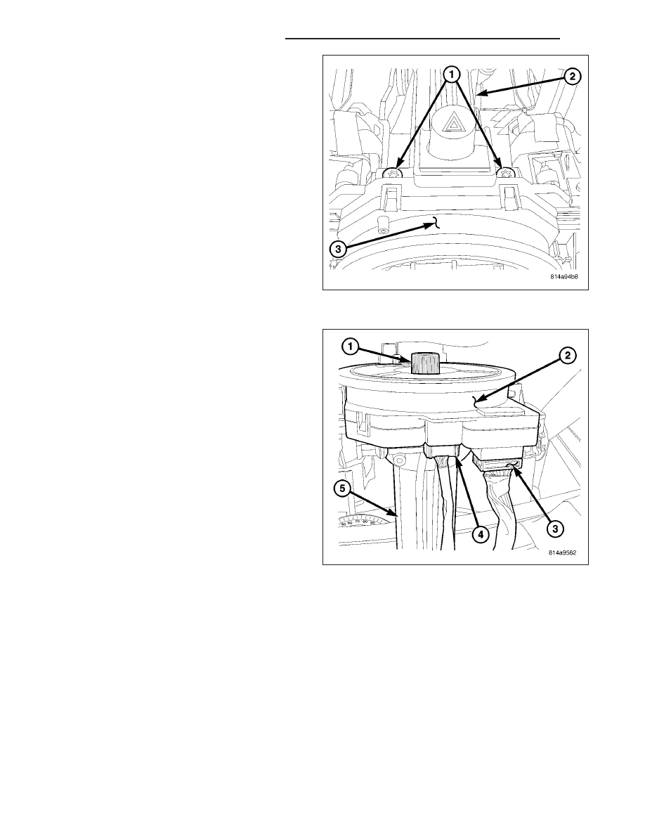
2. Tighten the two screws (1) securing the SCM (3) to

the column shaft housing.

3. Connect the two electrical connectors (3 & 4) to the

SCM (2).

19 - 58

COLUMN - SERVICE INFORMATION

WK

4. Install the steering column shrouds (1 & 2) (Refer

to

19

-

STEERING/COLUMN/SHROUD

-

INSTALLATION).

5. Align the spline on the steering wheel hub to shaft

(5) and install the steering wheel (3). (Refer to 19 -
STEERING/COLUMN/STEERING

WHEEL

-

INSTALLATION).

6. Install a NEW retaining bolt (4). Torque the bolt to

61 N·m (45 ft. lbs.).

7. Install the driver airbag (Refer to 8 - ELECTRICAL/

RESTRAINTS/DRIVER AIRBAG - INSTALLATION).

8. Connect the battery negative cable.

NOTE: IF EQUIPPED WITH ESP - recalibrate the
steering angle sensor using the scan tool (Refer to
8 - ELECTRICAL/BATTERY SYSTEM - STANDARD
PROCEDURE).

WK

COLUMN - SERVICE INFORMATION

19 - 59

GEAR - SERVICE INFORMATION

TABLE OF CONTENTS

page

page

GEAR - SERVICE INFORMATION

DESCRIPTION

. . . . . . . . . . . . . . . . . . . . . . . . . 60

OPERATION

. . . . . . . . . . . . . . . . . . . . . . . . . . . 60

REMOVAL

. . . . . . . . . . . . . . . . . . . . . . . . . . . . . 60

INSTALLATION

. . . . . . . . . . . . . . . . . . . . . . . . . 63

SPECIFICATIONS

TORQUE CHART

. . . . . . . . . . . . . . . . . . . . . . 66

GEAR - SERVICE INFORMATION

DESCRIPTION

A rack and pinion steering gear is made up of two
main components, the pinon shaft and the rack. The
gear cannot be adjusted or internally serviced. If a
malfunction or a fluid leak occurs, the gear must be
replaced as an assembly.

OPERATION

The steering column intermediate shaft is attached to the gear pinion. The rotation of the pinion moves the gear
rack from side-to-side. This lateral action of the rack pushes and pulls the tie rods, which are connected to the
steering knuckles to change the direction of the front wheels.

REMOVAL

1. Place the front wheels in the straight ahead posi-

tion with the steering wheel centered and locked
with a steering wheel lock.

2. Drain or siphon the power steering system.

3. Remove the column coupler shaft bolt (2) and

remove the shaft from the gear (3).

19 - 60

GEAR - SERVICE INFORMATION

WK

4. Remove the oil drip tray (1).

5. Remove the pressure line (2) at the gear (1).

6. Remove the return line (3) at the gear (1).

7. Raise and support the vehicle.

8. Remove the front tires.

WK

GEAR - SERVICE INFORMATION

19 - 61


Content   ..  1284  1285  1286  1287   ..