Jeep Grand Cherokee WK. Manual - part 1260


  Index      Jeep     Jeep Grand Cherokee WK - service repair manual 2005 year


Search            


Content   ..  1258  1259  1260  1261   ..


Jeep Grand Cherokee WK. Manual - part 1260


RAIL-FUEL

DESCRIPTION

The fuel injector rail is used to mount the fuel injectors to the engine.

OPERATION

High pressure from the fuel pump is routed to the fuel rail. The fuel rail then supplies the necessary fuel to each
individual fuel injector.

A quick-connect fitting with a safety latch clip is used to attach the fuel line to the fuel rail.

The fuel rail is not repairable.

CAUTION: The left and right sections of the fuel rail are connected with either a flexible connecting hose, or
joints. Do not attempt to separate the rail halves at these connecting hose or joints. Due to the design of
the connecting hose or joint, it does not use any clamps. Never attempt to install a clamping device of any
kind to the hose or joint. When removing the fuel rail assembly for any reason, be careful not to bend or
kink the connecting hose or joint.

REMOVAL

3.7L V-6

WARNING: THE FUEL SYSTEM IS UNDER CONSTANT PRESSURE EVEN WITH ENGINE OFF. BEFORE SER-
VICING FUEL RAIL, FUEL SYSTEM PRESSURE MUST BE RELEASED.

CAUTION: The left and right fuel rails are replaced as an assembly. Do not attempt to separate rail halves
at connector tubes. Due to design of tubes, it does not use any clamps. Never attempt to install a clamping
device of any kind to tubes. When removing fuel rail assembly for any reason, be careful not to bend or
kink tubes.

1. Remove fuel tank filler tube cap.

2. Perform Fuel System Pressure Release Procedure.

3. Remove negative battery cable at battery.

4. Remove air duct at throttle body air box.

5. Remove air box at throttle body.

6. Remove air resonator mounting bracket at front of

throttle body (2 bolts).

7. Disconnect fuel line latch clip and fuel line at fuel

rail. A special tool will be necessary for fuel line
disconnection. Refer to Quick-Connect Fittings.

8. Remove necessary vacuum lines at throttle body.

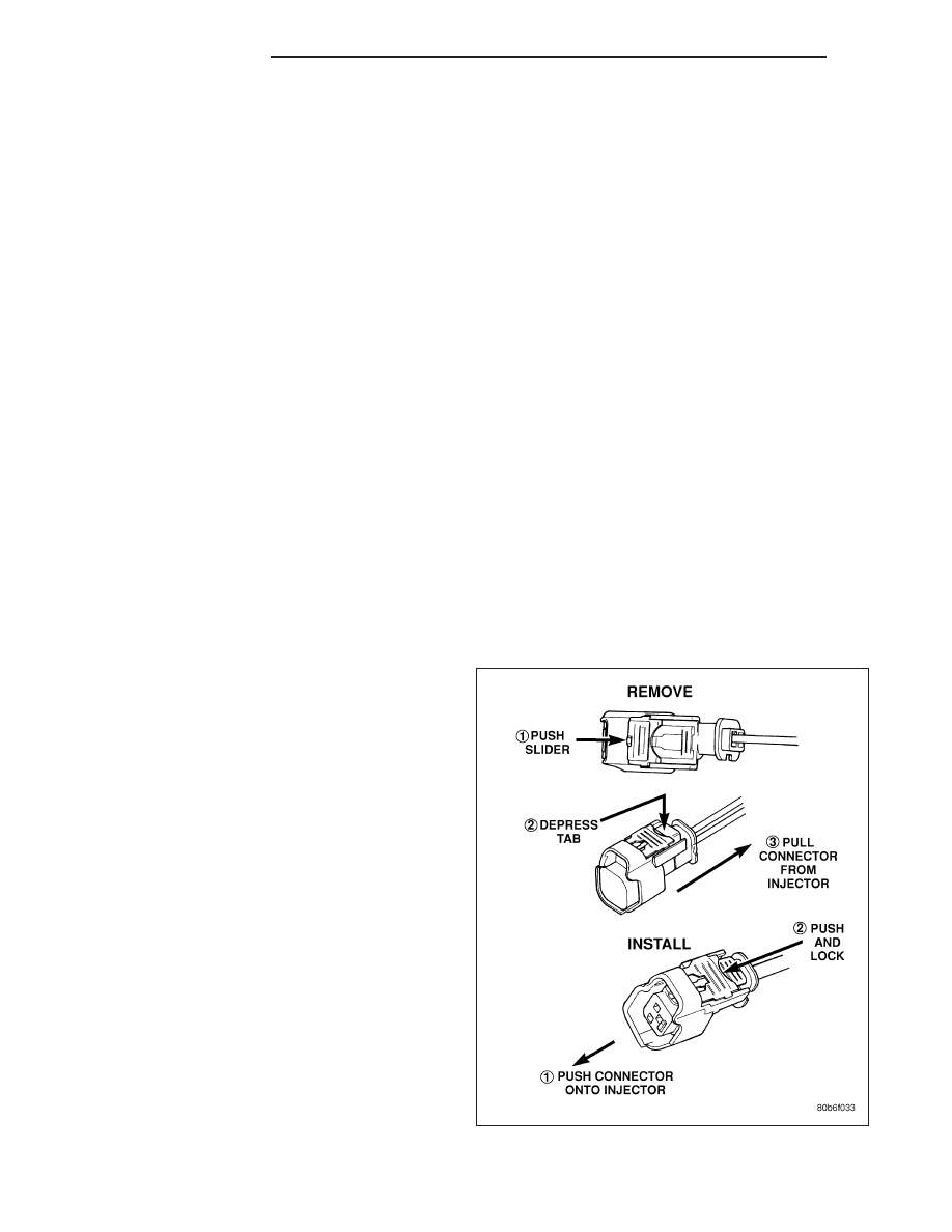
9. Disconnect electrical connectors at all 6 fuel injec-

tors. Refer to graphic. Push red colored slider away
from injector (1). While pushing slider, depress tab
(2) and remove connector (3) from injector. The
factory fuel injection wiring harness is numerically
tagged (INJ 1, INJ 2, etc.) for injector position iden-
tification. If harness is not tagged, note wiring loca-
tion before removal.

10. Disconnect electrical connectors at all throttle

body sensors.

11. Remove 6 ignition coils. Refer to Ignition Coil

Removal/Installation.

14 - 14

FUEL DELIVERY

WK

12. Remove four fuel rail mounting bolts (1).

13. Gently rock and pull left side of fuel rail until fuel

injectors just start to clear machined holes in cyl-
inder head. Gently rock and pull right side of rail
until injectors just start to clear cylinder head
holes. Repeat this procedure (left/right) until all
injectors have cleared cylinder head holes.

14. Remove fuel rail (with injectors attached) from

engine.

15. If fuel injectors are to be removed, refer to Fuel

Injector Removal/Installation.

4.7L V-8

WARNING: THE FUEL SYSTEM IS UNDER CONSTANT PRESSURE EVEN WITH ENGINE OFF. BEFORE SER-
VICING FUEL RAIL, FUEL SYSTEM PRESSURE MUST BE RELEASED.

CAUTION: The left and right fuel rails are replaced as an assembly. Do not attempt to separate rail halves
at connector tubes. Due to design of tubes, it does not use any clamps. Never attempt to install a clamping
device of any kind to tubes. When removing fuel rail assembly for any reason, be careful not to bend or
kink tubes.

1. Remove fuel tank filler tube cap.

2. Perform Fuel System Pressure Release Procedure.

3. Remove negative battery cable at battery.

4. Remove air duct at throttle body air box.

5. Remove air box at throttle body.

6. Remove air resonator mounting bracket at front of

throttle body (2 bolts).

7. Disconnect fuel line latch clip and fuel line at fuel

rail. A special tool will be necessary for fuel line
disconnection. Refer to Quick-Connect Fittings.

8. Remove necessary vacuum lines at throttle body.

9. Disconnect electrical connectors at all 8 fuel injec-

tors. Refer to graphic. Push red colored slider away
from injector (1). While pushing slider, depress tab
(2) and remove connector (3) from injector. The
factory fuel injection wiring harness is numerically
tagged (INJ 1, INJ 2, etc.) for injector position iden-
tification. If harness is not tagged, note wiring loca-
tion before removal.

10. Disconnect electrical connectors at all throttle

body sensors.

11. Remove 8 ignition coils. Refer to Ignition Coil

Removal/Installation.

WK

FUEL DELIVERY

14 - 15

12. Remove 4 fuel rail mounting bolts (1).

13. Gently rock and pull left side of fuel rail until fuel

injectors just start to clear machined holes in cyl-
inder head. Gently rock and pull right side of rail
until injectors just start to clear cylinder head
holes. Repeat this procedure (left/right) until all
injectors have cleared cylinder head holes.

14. Remove fuel rail (with injectors attached) from

engine.

15. If fuel injectors are to be removed, refer to Fuel

Injector Removal/Installation.

5.7L V-8

WARNING: THE FUEL SYSTEM IS UNDER CONSTANT PRESSURE EVEN WITH ENGINE OFF. BEFORE SER-
VICING FUEL RAIL, FUEL SYSTEM PRESSURE MUST BE RELEASED.

CAUTION: The left and right fuel rails are replaced as an assembly. Do not attempt to separate rail halves
at connector tube. Due to design of tube, it does not use any clamps. Never attempt to install a clamping
device of any kind to tube. When removing fuel rail assembly for any reason, be careful not to bend or kink
tube.

14 - 16

FUEL DELIVERY

WK

1. Remove fuel tank filler tube cap.

2. Perform Fuel System Pressure Release Procedure.

3. Remove negative battery cable at battery.

4. Remove flex tube (air cleaner housing to engine).

5. Remove air resonator box at throttle body.

6. Disconnect all spark plug cables from all spark plugs and ignition coils. Do not remove cables from cable routing

tray. Note original cable positions while removing.

1 - #8 COIL-TO- #5 SPARK PLUG (MARKED 5/8)

7 - CABLE TRAY

2 - #5 COIL-TO- #8 SPARK PLUG (MARKED 5/8)

8 - CLIPS (SPARK PLUG CABLE-TO-TRAY- RETENTION)

3 - #7 COIL-TO- #4 SPARK PLUG (MARKED 4/7)

9 - #2 COIL-TO- #3 SPARK PLUG (MARKED 2/3)

4 - #3 COIL-TO- #2 SPARK PLUG (MARKED 2/3)

10 - #6 COIL-TO- #1 SPARK PLUG (MARKED 1/6)

5 - #1 COIL-TO- #6 SPARK PLUG (MARKED 1/6)

11 - #4 COIL-TO- #7 SPARK PLUG (MARKED 4/7)

6 - CLIPS (TRAY-TO-MANIFOLD RETENTION)

WK

FUEL DELIVERY

14 - 17


Content   ..  1258  1259  1260  1261   ..