Jeep Grand Cherokee WK. Manual - part 1239


  Index      Jeep     Jeep Grand Cherokee WK - service repair manual 2005 year


Search            


Content   ..  1237  1238  1239  1240   ..


Jeep Grand Cherokee WK. Manual - part 1239


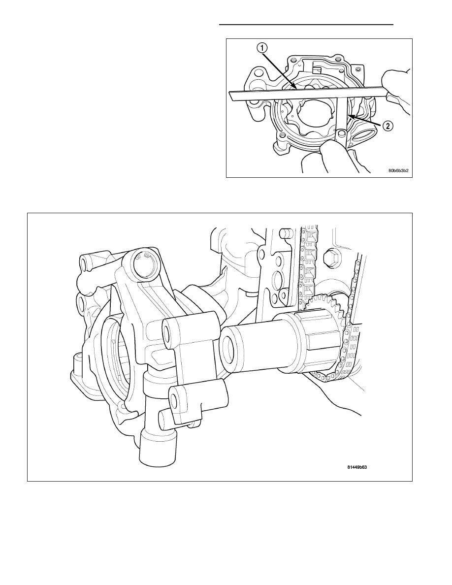
5. Place a straight edge (1) across the body of the oil

pump (between the bolt holes), if a feeler gauge (2)
of .095 mm (0.0038 in.) or greater can be inserted
between the straightedge and the rotors, the pump
must be replaced.

6. Reinstall the pump cover. Torque fasteners to 15

N·m (132 in. lbs.).

NOTE: The 5.7 Oil pump is released as an assem-
bly. There are no DaimlerChrysler part numbers for
Sub-Assembly components. In the event the oil
pump is not functioning or out of specification it
must be replaced as an assembly.

INSTALLATION

1. Position the oil pump onto the crankshaft and install the 4 oil pump retaining bolts.

2. Tighten the oil pump retaining bolts to 28 N·m (250 in. lbs.).

3. Install the timing chain cover (Refer to 9 - ENGINE/VALVE TIMING/TIMING BELT / CHAIN COVER(S) - INSTAL-

LATION).

4. Install the pick-up tube and oil pan (Refer to 9 - ENGINE/LUBRICATION/OIL PAN - INSTALLATION).

9 - 1552

ENGINE - 5.7L SERVICE INFORMATION

WK

MANIFOLD - INTAKE

DESCRIPTION

The intake manifold is made of a composite material and features long runners which maximizes low end torque.
The intake manifold uses single plane sealing which consist of eight individual press in place port gaskets to prevent
leaks.

DIAGNOSIS AND TESTING - INTAKE MANIFOLD LEAKAGE

An intake manifold air leak is characterized by lower than normal manifold vacuum. Also, one or more cylinders may
not be functioning.

WARNING: USE EXTREME CAUTION WHEN THE ENGINE IS OPERATING. DO NOT STAND IN A DIRECT LINE
WITH THE FAN. DO NOT PUT YOUR HANDS NEAR THE PULLEYS, BELTS OR THE FAN. DO NOT WEAR
LOOSE CLOTHING.

1. Start the engine.

2. Spray a small stream of water at the suspected leak area.

3. If a change in RPM is observed the area of the suspected leak has been found.

4. Repair as required.

REMOVAL

1. Remove engine cover (1).

2. Bleed fuel system (Refer to 14 - FUEL SYSTEM/

FUEL DELIVERY - STANDARD PROCEDURE).

3. Disconnect negative cable from battery.

4. Remove air inlet hose.

5. Remove ignition wires from on top of intake

manifold.

6. Disconnect electrical connectors for the following components:

Manifold Absolute Pressure (MAP) Sensor

Fuel Injectors

ETC ( Electric Throttle Control )

7.

Remove wire harness from intake manifold.

8. Disconnect brake booster hose, purge hose, and MUA hose ( Make Up Air Hose ).

9. Remove EGR tube from intake manifold.

10. Remove intake manifold retaining fasteners in a crisscross pattern starting from the outside bolts and ending at

the middle bolts.

WK

ENGINE - 5.7L SERVICE INFORMATION

9 - 1553

11. Remove intake manifold as an assembly.

CLEANING

NOTE: There is NO approved repair procedure for the intake manifold. If severe damage is found during
inspection, the intake manifold must be replaced.

Before installing the intake manifold thoroughly clean the mating surfaces. Use a suitable cleaning solvent, then air
dry.

INSPECTION

1. Inspect the intake sealing surface for cracks, nicks and distortion.

2. Inspect the intake manifold vacuum hose fittings for looseness or blockage.

INSTALLATION

1. Position intake manifold.

2. Install intake manifold retaining bolts, and tighten in sequence from the middle bolts towards the outside in a

crisscross pattern. Torque fasteners to 12 N·m (105 in. lbs.).

3. Install EGR tube.

4. Install wire harness on intake manifold.

5. Connect electrical connectors for the following components:

Manifold Absolute Pressure (MAP) Sensor

Fuel Injectors

ETC ( Electronic Throttle Control )

6. Install ignition wires.

7. Connect Brake booster hose, purge hose, and

MUA hose ( Make Up Air hose ).

8. Install air inlet hose.

9. Connect negative cable to battery.

10. Install engine cover (1).

MANIFOLD - EXHAUST

DESCRIPTION

The exhaust manifolds are log style with a patented flow enhancing design to maximize performance. The exhaust
manifolds are made of high silicon molybdenum cast iron. A multi-layer stainless steel exhaust manifold gasket is
used to improve sealing to the cylinder head. The exhaust manifolds are covered by a three layer laminated heat
shield for thermal protection and noise reduction. The heat shields are fastened with a torque prevailing nut that is

9 - 1554

ENGINE - 5.7L SERVICE INFORMATION

WK

backed off slightly to allow for the thermal expansion of the exhaust manifold, with the exception of the nut, which
also secures the oil dipstick tube bracket. That nut should not be backed off.

OPERATION

The exhaust manifolds collect the engine exhaust exiting the combustion chambers, then channels the exhaust
gases to the exhaust pipes attached to the manifolds.

REMOVAL

EXHAUST MANIFOLD

1. Disconnect negative battery cable.

2. Raise vehicle.

3. Remove exhaust pipe to manifold bolts.

4. Remove engine mount to frame fasteners (3,4).

5. Using suitable jack, raise engine enough to remove manifolds.

CAUTION: Do not damage engine harness while raising the engine.

6. Remove the engine mount (Refer to 9 - ENGINE/ENGINE MOUNTING/FRONT MOUNT - REMOVAL).

WK

ENGINE - 5.7L SERVICE INFORMATION

9 - 1555


Content   ..  1237  1238  1239  1240   ..