Jeep Grand Cherokee WK. Manual - part 1233


  Index      Jeep     Jeep Grand Cherokee WK - service repair manual 2005 year


Search            


Content   ..  1231  1232  1233  1234   ..


Jeep Grand Cherokee WK. Manual - part 1233


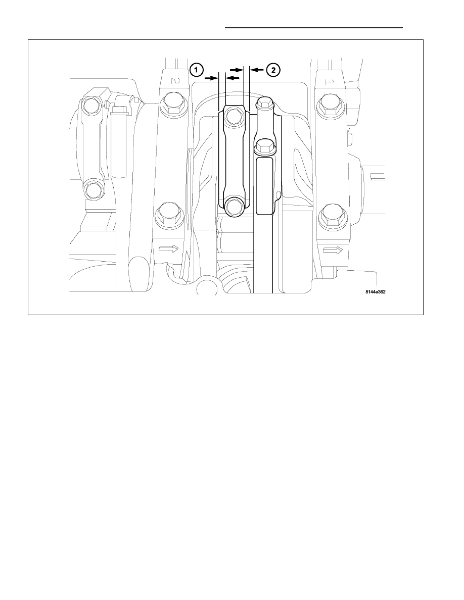
CAUTION: Connecting Rod Bolts are Torque to Yield Bolts and Must Not Be Reused. Always replace the
Rod Bolts whenever they are loosened or removed.

9. Lubricate rod bolts and bearing surfaces with engine oil. Install connecting rod cap and bearing. Tighten bolts to

21 N·m (15 ft. lbs.) plus a 90° turn.

10. Install the following components:

Cylinder head(s). (Refer to 9 - ENGINE/CYLINDER HEAD - INSTALLATION).

Cylinder head covers (Refer to 9 - ENGINE/CYLINDER HEAD/CYLINDER HEAD COVER(S) - INSTALLA-
TION).

Install the intake manifold.

Oil pan and gasket/windage tray. (Refer to 9 - ENGINE/LUBRICATION/OIL PAN - INSTALLATION).

11. Fill crankcase with proper engine oil to correct level.

12. Connect negative cable to battery.

RINGS-PISTON

STANDARD PROCEDURE - PISTON RING FITTING

Before reinstalling used rings or installing new rings, the ring clearances must be checked.

1. Wipe the cylinder bore clean.

2. Insert the ring in the cylinder bore.

9 - 1528

ENGINE - 5.7L SERVICE INFORMATION

WK

NOTE: The ring gap measurement must be made
with the ring positioned at least 12mm (0.50 inch.)
from bottom of cylinder bore.

3. Using a piston, to ensure that the ring is squared in

the cylinder bore, slide the ring downward into the
cylinder.

4. Using a feeler gauge check the ring end gap.

Replace any rings not within specification.

PISTON RING SIDE CLEARANCE

NOTE: Make sure the piston ring grooves are
clean and free of nicks and burrs.

5. Measure the ring side clearance as shown make

sure the feeler gauge fits snugly between the ring
land and the ring. Replace any ring not within
specification.

6. Rotate the ring around the piston, the ring must

rotate in the groove with out binding.

WK

ENGINE - 5.7L SERVICE INFORMATION

9 - 1529

PISTON RING SPECIFICATION CHART

Ring Position

Ring/Groove

Maximum

Side Clearance

Clearance

Upper Ring

0.02-0.07mm

0.11mm

(0.0008- 0.0028 in.)

(0.004 in.)

Intermediate Ring

0.02-0.06 mm

0.10mm

(0.0008-0.0023 in.)

(0.004 in.)

Ring Position

Ring Gap

Wear Limit

Upper Ring

0.23-0.38mm

0.43mm

(0.0090-0.0149 in.)

(0.017 in.)

Intermediate Ring

0.35-0.60mm

0.74mm

(0.0137-0.0236 in.)

(0.029 in.)

Oil Control Ring

0.015-0.66mm

0.76mm

(Steel Rail)

(0.0059- 0.0259 in.)

(0.030 in.)

7. The No. 1 and No. 2 piston rings have a different cross section. Ensure No. 2 ring is installed with manufacturers

I.D. mark (Dot) facing up, towards top of the piston.

NOTE: Piston rings are installed in the following order:

Oil ring expander.

Lower oil ring side rail.

Upper oil ring side rail.

No. 2 Intermediate piston ring.

No. 1 Upper piston ring.

8. Install the oil ring expander.

9. Install upper side rail by placing one end between

the piston ring groove and the expander ring. Hold
end firmly and press down the portion to be
installed until side rail is in position. Repeat this
step for the lower side rail.

9 - 1530

ENGINE - 5.7L SERVICE INFORMATION

WK

10. Install No. 2 intermediate piston ring using a pis-

ton ring installer.

11. Install No. 1 upper piston ring using a piston ring

installer.

12. Position piston ring end gaps as shown in. It is

important that expander ring gap is at least 45°
from the side rail gaps, but not on the piston pin
center or on the thrust direction.

DAMPER-CRANKSHAFT

REMOVAL

1. Disconnect negative cable from battery.

2. Remove accessory drive belt (Refer to 7 - COOLING/ACCESSORY DRIVE/DRIVE BELTS - REMOVAL).

3. Drain cooling system (Refer to 7 - COOLING - STANDARD PROCEDURE).

4. Remove radiator upper hose.

5. Remove fan shroud (Refer to 7 - COOLING/ENGINE/RADIATOR FAN - REMOVAL).

6. Remove crankshaft damper bolt.

WK

ENGINE - 5.7L SERVICE INFORMATION

9 - 1531


Content   ..  1231  1232  1233  1234   ..