Jeep Grand Cherokee WK. Manual - part 1221


  Index      Jeep     Jeep Grand Cherokee WK - service repair manual 2005 year


Search            


Content   ..  1219  1220  1221  1222   ..


Jeep Grand Cherokee WK. Manual - part 1221


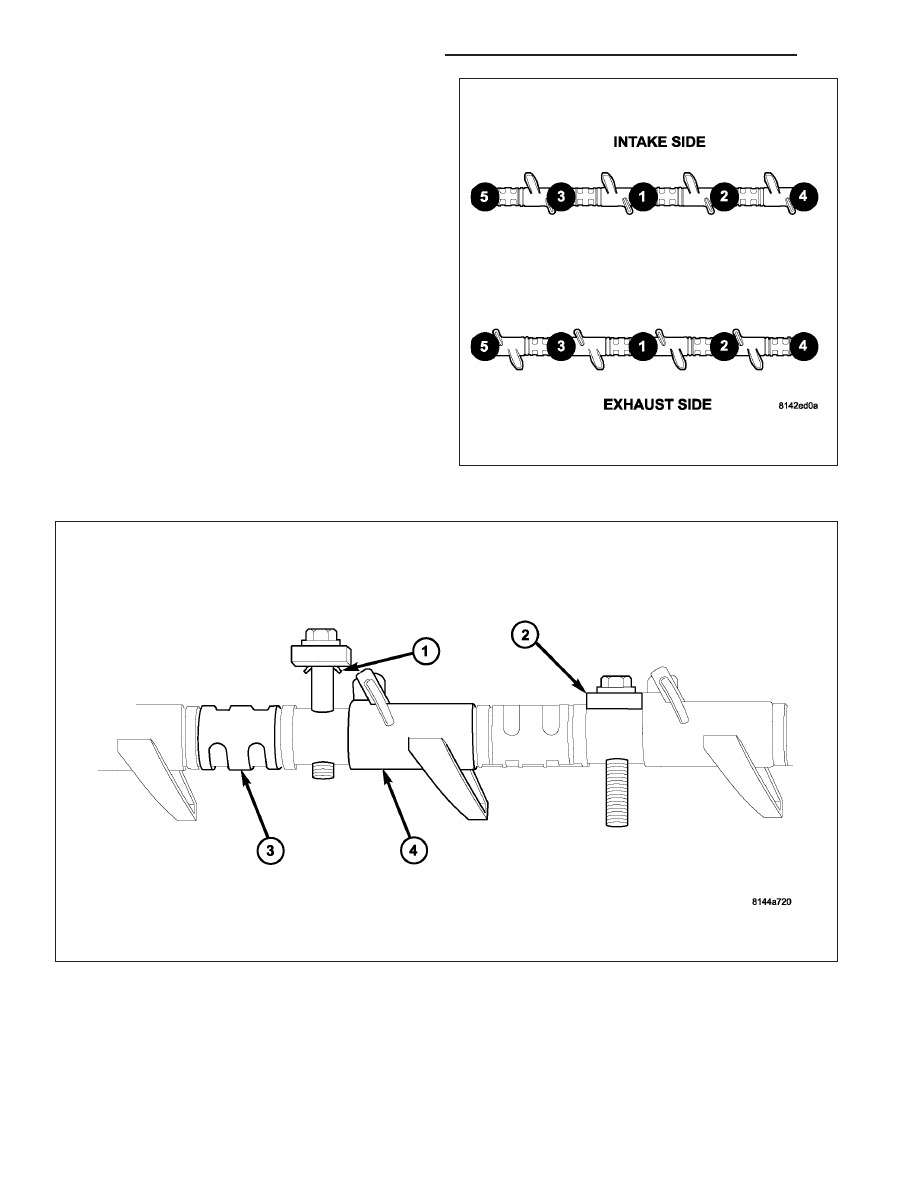
3. Loosen the rocker shafts using the sequence pro-

vided.

CAUTION: The rocker shaft assemblies are not
interchangeable between intake and exhaust. The
intake rocker arms are marked with an “I”.

4. Remove the rocker shafts. Note location for reas-

sembly.

CAUTION: The longer push rods are for the
exhaust side, and the shorter push rods are for
intake side.

5. Remove the pushrods. Note pushrod location for

reassembly.

9 - 1480

ENGINE - 5.7L SERVICE INFORMATION

WK

CAUTION: Do not remove the retainers from the rocker shaft. The assembly tangs (1) at the bottom of the
retainers (2) can be damaged, causing the assembly tangs to break off, and get into the engine.

INSTALLATION

CAUTION: The longer push rods are for the
exhaust side, and the shorter push rods are for
intake side.

1. Install the push rods in the same order as

removed.

2. Install the pushrod retaining plate (1) special tool

9070.

CAUTION: Ensure that retainers (2) and rocker arms (4) are not overlapped when torquing bolts.

WK

ENGINE - 5.7L SERVICE INFORMATION

9 - 1481

CAUTION: Verify that pushrod is installed into rocker arm (4) and tappet correctly while installing rocker
shaft assembly. Recheck after rocker shaft has been torqued to specification.

CAUTION: The rocker shaft assemblies are not
interchangeable between intake and exhaust. The
intake rocker arms are marked with the letter “I”.

3. Install rocker shaft assemblies in the same order

as removed.

4. Tighten the rocker shaft bolts to 22 N·m (195 in.

lbs.) torque,using the sequence provided.

CAUTION: DO NOT rotate or crank the engine dur-
ing or immediately after rocker arm installation.
Allow the hydraulic roller tappets adequate time to
bleed down (about 5 minutes).

5. Remove pushrod retaining plate (1) special tool

9070.

9 - 1482

ENGINE - 5.7L SERVICE INFORMATION

WK

6. Install cylinder head cover (Refer to 9 - ENGINE/

CYLINDER HEAD/CYLINDER HEAD COVER(S) -
INSTALLATION).

SEALS-VALVE GUIDE

DESCRIPTION

The valve guide seals are made of rubber and incorporate an integral steel valve spring seat. The integral garter
spring maintains consistent lubrication control to the valve stems.

SPRINGS-VALVE

REMOVAL

1. Disconnect negative battery cable.

2. Remove air cleaner assembly.

3. Remove air intake resonator.

4. Remove spark plug cables.

5. Remove ignition coil connectors (4).

6. Remove ignition coils (5).

7. Remove one spark plug.

WK

ENGINE - 5.7L SERVICE INFORMATION

9 - 1483


Content   ..  1219  1220  1221  1222   ..